

From Product Idea to Reviewable Schematic
Most AI diagram tools can draw a circuit-like picture. That is useful for brainstorming, but it is not enough for engineering work. A real electronics project needs power rails, interfaces, IC choices, connectors, net structure, schematic hierarchy, BOM notes, and files that can move into an EDA workflow.
SpeedUp is an AI circuit schematic generator built for that handoff. You write the product requirement in plain language, and SpeedUp creates a circuit design draft with organized schematic sheets and a downloadable KiCad project. The result is not a replacement for engineering review. It is a faster way to get from "we should build this" to a concrete design package that an engineer can inspect.
What SpeedUp Generates
| Output | What it is for | Why it matters |
|---|---|---|
| System architecture | A block-level view of power, control, sensing, communication, and user I/O | Helps the team agree on the device structure before reviewing details |
| Schematic sheets | Organized circuit sheets for major functional blocks | Makes review easier than a single flat drawing |
| Component and BOM context | Suggested parts, functional roles, and sourcing notes where available | Gives engineers a starting point for cost, availability, and substitutions |
| KiCad project package | Editable design files that can be opened in KiCad | Keeps the output useful beyond a screenshot or static diagram |
| Review notes | Areas that still need engineering validation | Keeps the workflow honest before layout, sourcing, testing, or production |
Built for Electronics, Not Generic Diagrams
If you search for an AI schematic generator today, many results are general diagram generators. They can turn text into boxes, arrows, flowcharts, or simple circuit visuals. SpeedUp focuses on a narrower and more useful job: generating electronics design drafts that can become real KiCad schematic projects.
That difference matters when the product is more than a toy circuit. A USB-C device, BLE sensor, power bank, e-ink display, or FPGA power system needs more than a nice-looking diagram. It needs power budgeting, connector choices, interface assumptions, pullups, protection, decoupling, clocking, debug access, mechanical constraints, and a BOM that can survive review.
SpeedUp is designed for that middle step between product idea and manual schematic work.
How It Works
1. Describe the device
Start with a product-level prompt. For example:
Design a battery-powered BLE temperature and humidity sensor with USB-C charging, low-power sleep, status LED, programming header, and a compact KiCad schematic.
You can include constraints such as battery type, target voltage rails, preferred MCU family, interfaces, enclosure limits, expected sensors, charging behavior, or communication requirements.
2. SpeedUp creates the architecture
SpeedUp breaks the product into engineering blocks: power management, MCU or processor, sensors, communication, user interface, connectors, debug, storage, and protection. This architecture gives the team a shared map before diving into individual schematic sheets.
3. Review the generated schematic sheets
The generated schematic is organized for review. Engineers can inspect the power tree, signal interfaces, bus pullups, connectors, protection components, boot/debug access, component choices, and unresolved assumptions.
4. Open the KiCad project
Instead of stopping at a PNG or PDF, SpeedUp provides a KiCad project package. For the KiCad-specific workflow, see the AI KiCad schematic generator. That means the design can continue in a familiar EDA tool where engineers can adjust symbols, footprints, component values, layout constraints, and manufacturing preparation.
Where an AI Schematic Generator Helps Most
SpeedUp is strongest when you know the device you want, but do not want to start from a blank schematic.
| Use case | Good fit for SpeedUp? | Notes |
|---|---|---|
| Product concept to first schematic draft | Yes | Best when requirements are specific enough to define power, interfaces, and device behavior |
| Comparing architecture options | Yes | Useful for trying alternate MCU, power, sensor, or communication approaches |
| Creating a review package for an engineer | Yes | The generated KiCad files and BOM context make feedback more concrete |
| Final production release without review | No | Engineers still need to verify electrical, layout, sourcing, compliance, and safety details |
| Generic flowcharts or non-electronics diagrams | No | Use a general diagram tool for that |
Example: A Generated Charging Architecture
One SpeedUp-generated charging project shows the kind of architecture an engineer can review before touching layout. The generated design separates power distribution, DC input protection, the system controller, USB-C PD ports, USB-A fast charging, wireless charging, thermal sensing, and connector blocks.
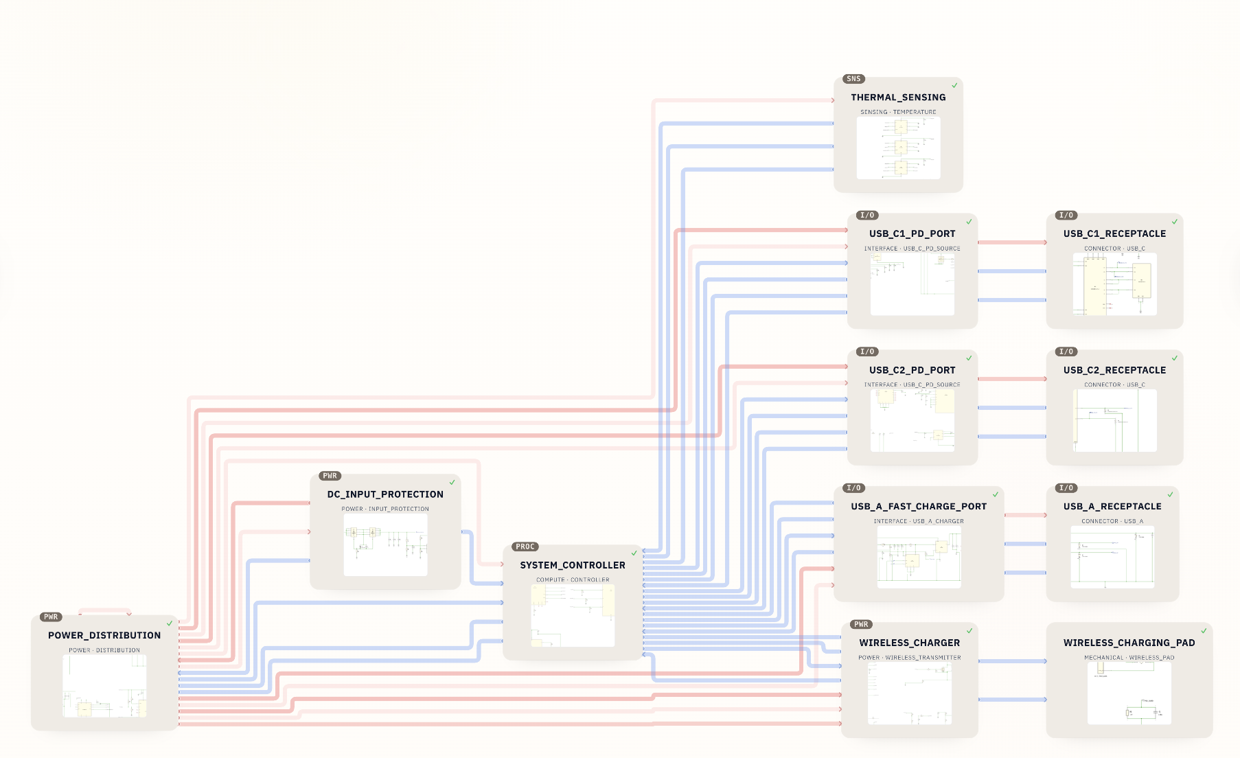
This is the kind of output that separates an electronics-focused AI schematic generator from a generic circuit diagram maker. The goal is not just to draw a battery and a USB-C connector. The goal is to produce a structured engineering draft that exposes the real questions: charger topology, cell configuration, port behavior, thermal risk, safety protections, and component selection.
What Engineers Should Still Review
AI schematic generation speeds up the first draft, but it does not remove engineering responsibility. Before using any generated design for layout, procurement, testing, certification, or production, review the design carefully.
| Review area | What to check | Typical questions |
|---|---|---|
| Power tree | Rails, load current, sequencing, efficiency, thermal limits | Are all loads powered from the right rail? Is the regulator sized correctly? |
| Battery and charging | Charger IC, protection, current limits, temperature sensing, cell configuration | Is the charging design safe for the selected battery chemistry? |
| Interfaces | I2C, SPI, UART, USB, display, sensor, debug, and connector assumptions | Are pullups, level shifting, ESD, pin mapping, and connector orientation correct? |
| Component choices | Availability, lifecycle, package, cost, alternate parts | Can the BOM be sourced today, and are footprints correct? |
| Layout constraints | High-current loops, RF, crystals, impedance, heat, creepage, keepouts | Does the schematic communicate the constraints a PCB designer needs? |
| Firmware assumptions | Boot pins, programming header, reset behavior, low-power states | Can firmware bring-up and debugging happen on the first board? |
| Compliance and safety | USB-C behavior, battery safety, EMI, thermal, regulatory constraints | Is additional validation or certified module use required? |
SpeedUp vs. Generic AI Circuit Diagram Tools
| Capability | Generic diagram generator | SpeedUp |
|---|---|---|
| Text prompt input | Usually yes | Yes |
| Electronics-specific architecture | Limited | Yes |
| Structured schematic sheets | Usually no | Yes |
| KiCad project output | Usually no | Yes |
| BOM context | Limited or absent | Included where available |
| Engineering review workflow | Not the focus | Core workflow |
| Best use | Explaining or visualizing an idea | Creating a reviewable electronics design draft |
Good Prompts Produce Better Schematics
For best results, write prompts like product requirements rather than one-line wishes.
Weak prompt:
Make a wearable sensor.
Better prompt:
Design a compact wearable temperature and motion sensor using a low-power BLE MCU, a rechargeable Li-ion battery, USB-C charging, one RGB status LED, an accelerometer, temperature sensing, SWD programming, and a KiCad schematic organized by power, MCU, sensors, charging, and connectors.
Include:
- Target use case
- Main functional blocks
- Power source and voltage rails
- Important ICs or preferred families
- Interfaces and connectors
- Size, battery, or enclosure constraints
- Safety, charging, RF, or compliance concerns
- Expected output format, such as KiCad
Related SpeedUp Examples
- Browse SpeedUp demo projects to see generated circuit designs from real prompts.
- See a desktop robot KiCad project generated from a prompt for a multi-board product example.
- Review the TWS earbuds schematic and charging case project for a compact consumer-electronics design.
- Use the AI schematic generator debugging tool circuit as an example of a tool-style hardware prompt.
- Compare against the low-cost portable Bluetooth speaker schematic for audio, battery, and amplifier blocks.
- Compare the workflow with the magnetic AI label microphone KiCad project, which shows how a product prompt becomes reviewable schematic evidence.
- Read the AI-generated KiCad schematic review guide before using generated files for layout or procurement.
- Inspect the nRF54L15 KiCad schematic project for a component-specific RF, power, and debug example.
- Use the battery-powered sensor circuit design checklist when your prompt involves sensors, batteries, and low-power constraints.
FAQ
What is an AI schematic generator?
An AI schematic generator turns a text description of an electronic device into a schematic draft. For engineering work, the useful version is not just a static image. It should produce organized circuit blocks, component context, and editable design files that engineers can review.
Can AI generate a real KiCad schematic?
Yes, AI can generate a first KiCad schematic draft when the prompt includes enough engineering detail. The output still needs human review for electrical correctness, component choices, footprints, layout constraints, sourcing, safety, and test planning.
Is SpeedUp the same as an AI circuit diagram generator?
Not exactly. Many AI circuit diagram generators focus on drawing a diagram. SpeedUp focuses on creating a structured electronics design package, including schematic sheets and a KiCad project that can continue into an engineering workflow.
Is the generated schematic ready for manufacturing?
Treat the generated schematic as a reviewable first draft, not an automatic production release. Engineers should validate the power design, interfaces, component values, BOM, footprints, layout constraints, thermal behavior, compliance needs, and test strategy before manufacturing.
What should I include in my prompt?
Include the device purpose, power source, target voltage rails, main chips or preferred part families, sensors, connectors, communication interfaces, battery or charging needs, mechanical constraints, and the output format you want. The more specific the requirements, the more useful the generated schematic draft will be.
Can I use SpeedUp for USB-C, BLE, sensors, displays, or power designs?
Yes. SpeedUp is a strong fit for multi-block electronics projects such as USB-C charging devices, BLE sensors, e-ink displays, power banks, small regulators, and embedded systems. More complex or safety-critical designs require deeper engineering review.
Generate Your Editable Circuit Schematic
Move from a product idea to structured schematic sheets and an editable KiCad project.
Use SpeedUp to turn the product requirements into structured schematic sheets and an editable KiCad first draft for engineering review. Create a free account to begin.
Comments
No comments yet.
Leave a Reply