
Quick Answer
AI PCB design software is not one category. Some tools help turn a product requirement into a schematic and BOM, some help place and route an already-defined PCB, some use code-first workflows, and some act more like review or research assistants. The right choice depends on where your hardware project is stuck.
If you are still translating a product idea into circuits, start with schematic generation: requirements, functional blocks, power tree, interfaces, components, and an editable KiCad project that an engineer can review. If you already have a clean schematic, footprints, board outline, constraints, and stackup, layout automation can help with placement and routing. SpeedUp fits the first job: describe the device you want to build and get a structured schematic project for review before layout.
Why AI PCB Design Software Is Easy to Miscompare
Search results for ai pcb design software mix very different promises. A reader may see layout automation, schematic generation, BOM generation, code-defined electronics, browser ECAD, review assistants, and broad EDA platforms on the same page.
That makes a simple "best tool" answer misleading. A PCB design workflow has several stages:
- product requirement and architecture
- circuit block selection
- schematic capture
- component and BOM review
- footprint assignment
- placement and routing
- DRC/ERC checks
- prototype bring-up and validation
- manufacturing output
AI can help at several of those stages, but no stage removes the need to review the next one. A strong AI-generated schematic can make layout easier. A weak schematic can make layout automation confidently route the wrong board.
The Main Types of AI PCB Design Software
| Software type | Best fit | What it needs from you | What to review before trusting the output |
|---|---|---|---|
| Product-prompt to schematic | Turning a device idea into functional blocks, schematics, and a KiCad starting point | Product requirements, power source, interfaces, constraints, and use case | Power tree, IC choices, bus wiring, boot/debug, connectors, footprints, BOM, and missing protections |
| Architecture to schematic and BOM | Converting a defined hardware architecture into component choices, schematics, and bill of materials | Functional requirements, input/output signals, size/cost/power targets, availability constraints | Component ratings, sourcing, derating, design rules, safety margin, export format, and review traceability |
| PCB layout automation | Placing and routing a PCB after the circuit, footprints, board outline, and constraints are known | Schematic, netlist, footprints, constraints, board shape, stackup, and design rules | Return paths, impedance, thermal behavior, connector access, antenna keepouts, manufacturability, and DRC |
| Browser-based AI ECAD | Fast collaboration around schematics, PCB work, parts, and project exploration | Team workflow, component libraries, project conventions, and review process | File ownership, export paths, editable outputs, library quality, and handoff to your normal toolchain |
| Code-first electronics | Versioning circuits as code and letting agents or scripts iterate on designs | Comfort with code, reusable components, package conventions, and CI/review workflow | Whether the generated design maps cleanly to schematic intent, physical constraints, and manufacturer outputs |
| Review and research assistants | Datasheet parsing, part research, design review prompts, and checklist generation | Existing project files or clear questions | Whether the suggestions are grounded in the actual schematic, layout, BOM, and datasheets |
Choosing where AI fits in your PCB workflow?
Describe the product behavior, required schematic artifacts, existing design inputs, layout constraints, and handoff expectations. Create a free account to start a reviewable, editable KiCad first draft.
The most important question is not "Which AI PCB design tool is best?" It is "Which part of my PCB workflow is undefined right now?"
When to Choose Schematic Generation First
Choose schematic-first AI when the product idea is real but the circuit is not yet organized. This is common when a founder, product team, firmware engineer, or mechanical designer knows what the device should do but does not yet have a clean electrical architecture.
Use this route when you need:
- a first version of the power tree
- MCU, sensor, display, wireless, storage, motor, audio, or connector blocks
- named interfaces such as I2C, SPI, UART, USB, CAN, BLE, or Wi-Fi
- a reviewable KiCad project instead of a static circuit image
- BOM and component intent that can be checked by an engineer
- a starting point for layout handoff
This is where SpeedUp is useful. You describe the device, then review the generated KiCad schematic project block by block. The output should be treated as a first engineering draft. It is not a certified reference design, and it should not skip human review.
When to Choose Layout Automation
Choose layout automation when the electrical intent is already defined. Layout tools can be powerful after you have a schematic, footprints, constraints, board outline, layer stack, keepouts, connector locations, and manufacturing rules.
Layout automation is the wrong first step if you are still unsure about:
- which ICs and modules belong in the design
- how the power tree should be structured
- what voltage and current each rail needs
- which buses connect each subsystem
- whether the footprints are correct
- where test points and debug access belong
- what mechanical constraints shape the board
In other words: layout automation accelerates a defined PCB problem. It does not fix an undefined circuit.
Example From a Real SpeedUp Project
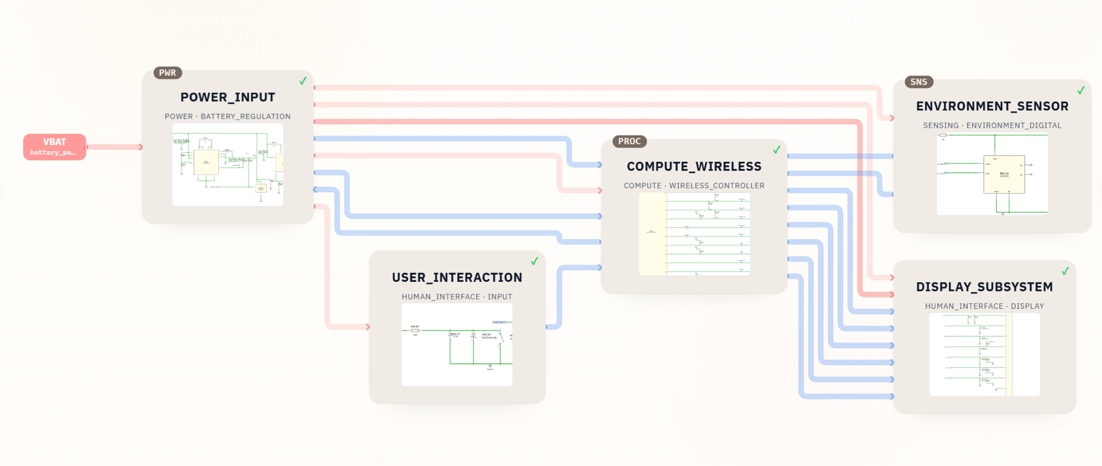
The Desktop Robot ESP32 KiCad schematic project shows the schematic-first workflow in practice. The project starts from a product-shaped requirement: a compact desktop robot controller with wireless control, display, sensing, user interface, and power input.
Instead of producing only a decorative circuit image, the generated output becomes a structured KiCad project with named sheets.
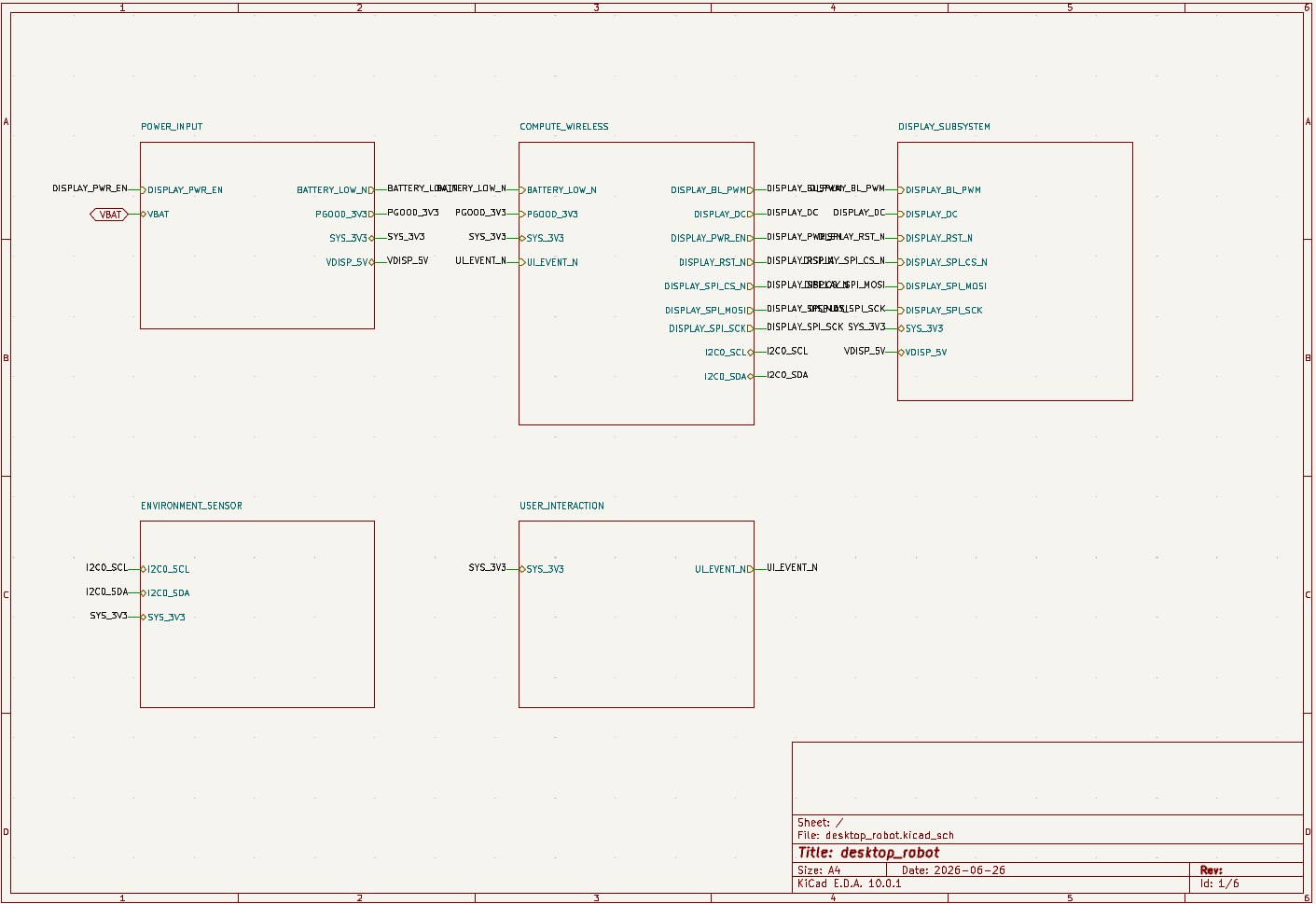
That matters because each block has different layout consequences. Power input and regulation affect thermal behavior and current paths. The wireless module affects antenna clearance. Display and sensor interfaces affect connector placement, signal naming, and firmware assumptions. User buttons and LEDs affect enclosure and panel decisions.
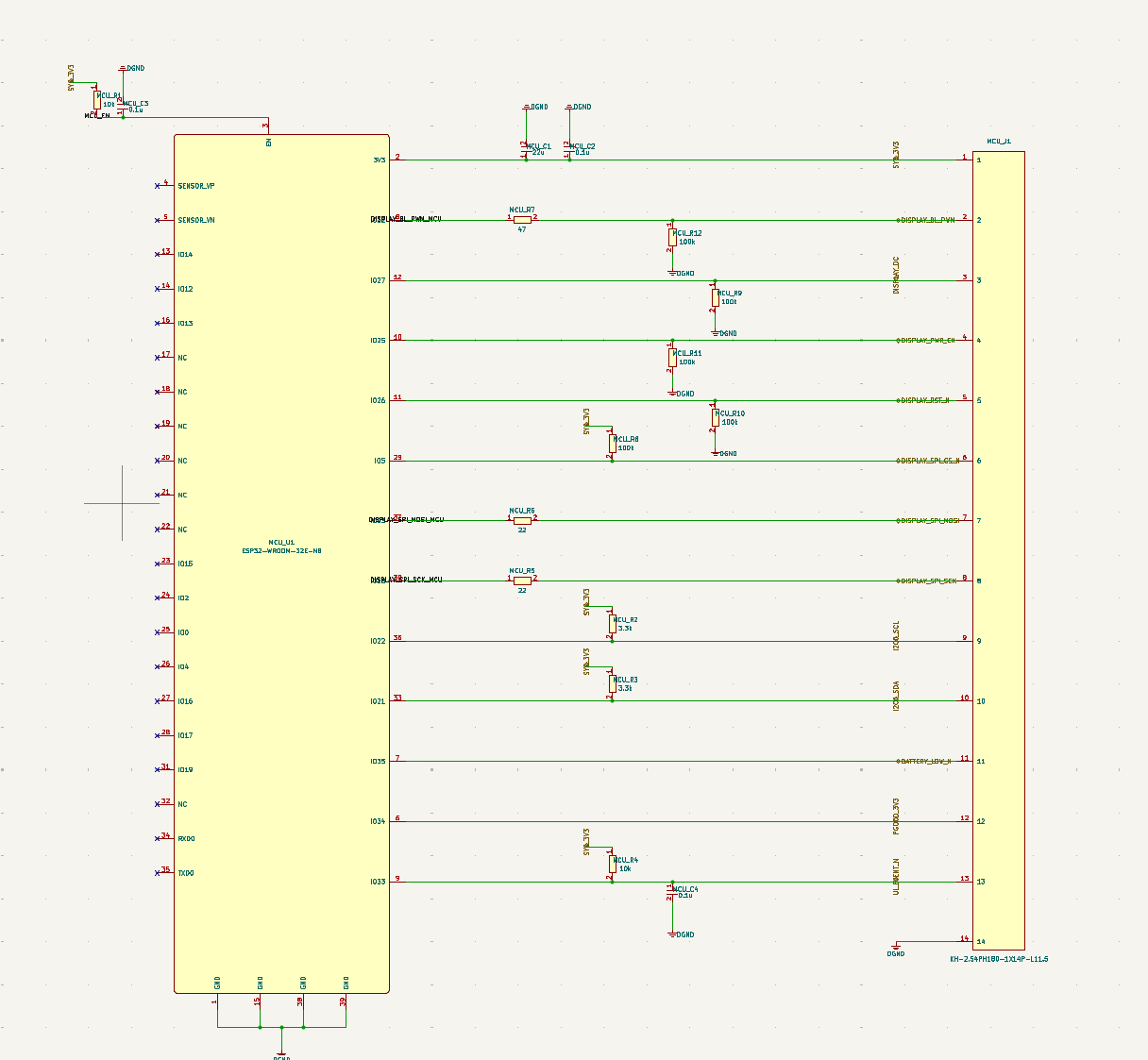
For this kind of project, schematic-first AI gives engineers a concrete object to review: sheets, nets, labels, components, and assumptions. Layout automation can come later, after the schematic and footprint choices survive review.
How to Compare AI PCB Design Software
Before choosing a tool, write down the handoff you need. Then compare tools by stage, not by hype.
| Question | Why it matters | Good sign |
|---|---|---|
| Does it generate editable engineering files? | Static images are hard to review, version, and reuse. | KiCad project, ECAD export, netlist, BOM, or structured source files |
| Does it start from requirements or from an existing schematic? | The input determines which stage the tool can help with. | Clear prompt, architecture, schematic, netlist, or layout-input requirements |
| Does it expose assumptions? | AI output needs traceability. | Named blocks, component rationale, review notes, and editable sheets |
| Does it support your normal toolchain? | A tool is less useful if the result cannot move into your review workflow. | KiCad, ECAD export, BOM export, versioning, or clear handoff files |
| Does it understand constraints? | PCB layout depends on mechanical, electrical, manufacturing, and thermal constraints. | Board outline, stackup, keepouts, impedance, placement, and design-rule inputs |
| Does it separate generation from validation? | AI suggestions are not proof. | DRC/ERC support, review checklist, test planning, and human approval points |
If a tool claims to do everything, look for the first file or decision you can actually inspect. A reviewable KiCad schematic, BOM, netlist, constraint set, or PCB file is more valuable than a vague promise.
Common Mistakes
- Comparing schematic-generation tools against layout-automation tools as if they solve the same problem.
- Asking AI for a finished PCB when the product requirement still lacks power, interface, and mechanical constraints.
- Treating a generated circuit image as a PCB design deliverable.
- Skipping footprint review because the schematic looks plausible.
- Ignoring connector placement, antenna keepouts, heat, grounding, current paths, and enclosure constraints until layout is already underway.
- Forgetting firmware and bring-up: boot pins, debug headers, test points, logging, update paths, and failure modes still matter.
- Assuming AI output is production-ready without DRC/ERC, layout review, prototype testing, sourcing checks, and compliance review.
How SpeedUp Fits
SpeedUp is best used when you have a device idea and need to move quickly toward a reviewable schematic project. It is not positioned as a one-click replacement for the whole PCB process. The practical value is earlier: product prompt to structured KiCad schematic draft.
That makes SpeedUp useful when your next question is:
- What should the first electrical architecture look like?
- Which blocks need to exist?
- How should the schematic be split?
- What should the engineer review before layout?
- Can this idea become a real KiCad project instead of a text description?
For layout, manufacturing, safety, compliance, and production, engineers still review and validate the design. The right mental model is acceleration with review, not blind automation.
Related SpeedUp Projects and Guides
- Desktop Robot ESP32 KiCad Schematic Project Generated from a Prompt – a product-shaped example with power, compute, display, sensing, BOM notes, and downloadable KiCad files.
- KiCad Schematic Generator: From Product Prompt to Editable KiCad Project – the core SpeedUp workflow for turning product requirements into a KiCad schematic draft.
- What to Check Before Using an AI-Generated KiCad Schematic for PCB Layout – a layout-readiness checklist for generated schematics.
- How to Review AI-Generated KiCad Schematics Before PCB Layout – a practical review process before a generated circuit moves downstream.
- AI Circuit Schematic Generator for KiCad Circuit Projects – a broader guide to AI schematic generation for KiCad projects.
FAQ
Which AI PCB design software is best?
The best choice depends on the stage. If you need a schematic from a product idea, choose a schematic-generation workflow. If you already have a circuit, board constraints, and footprints, choose layout automation. If your team works in code, a code-first electronics workflow may fit better. If you only need help reviewing or researching, use an assistant as a second layer rather than the source of truth.
Can AI design a complete PCB board?
AI can help draft parts of the PCB process, including architecture, schematic, BOM, review notes, placement, routing, and documentation. But a complete board still needs engineering review, footprint checks, DRC/ERC, layout inspection, prototype bring-up, sourcing review, and manufacturing validation.
Is schematic generation the same as PCB layout automation?
No. Schematic generation defines the circuit: parts, nets, power rails, interfaces, and functional blocks. PCB layout automation places and routes that circuit on a physical board. Layout depends on the schematic, footprints, constraints, board outline, stackup, and manufacturing rules being correct first.
Can ChatGPT do PCB design?
ChatGPT can help reason about requirements, architecture, checklists, and design review questions, but a real PCB workflow needs structured engineering outputs. For hardware work, look for editable schematics, KiCad files, BOMs, netlists, layout files, or verified constraints rather than text alone.
Why use SpeedUp instead of a layout-first AI tool?
Use SpeedUp when the first missing step is the schematic project. If you already have a reviewed schematic and constraints, layout-first tools may be more relevant. If you only have a product prompt, SpeedUp helps create the reviewable KiCad starting point that layout work needs later.
Start With the Right Engineering Artifact
Turn a product prompt into an editable schematic package before downstream PCB work begins.
Use SpeedUp to turn the product requirements into structured schematic sheets and an editable KiCad first draft for engineering review. Create a free account to begin.
Comments
No comments yet.
Leave a Reply