
Quick Answer
A good battery powered sensor circuit design should be reviewed in four layers: the energy path, the regulated supply rails, the sensor interface, and the user or data interface. For a small environmental sensor, that usually means checking the battery connector, USB-C or charging input, protection parts, buck or buck-boost regulator, MCU power states, I2C pullups, sensor placement, display current, and BOM readiness before the design moves to PCB layout.
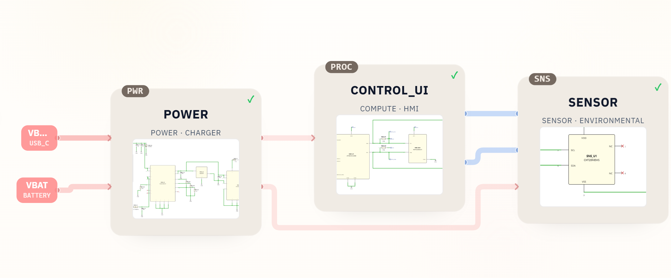
The fastest way to review the design is to start from the block diagram, then verify the top-level schematic, then inspect each subsystem sheet. In the example below, a SpeedUp-generated temperature and humidity sensor uses USB-C charging, a Li-ion battery path, a 3.3 V rail, an ATtiny controller, an OLED display, and a CHT20MEMS I2C temperature and humidity sensor. Treat this kind of generated schematic as a first engineering draft: useful for review and iteration, but not production-ready until an engineer validates parts, footprints, layout, firmware, safety, and calibration.
Why This Matters
Battery powered sensor products look simple, but small mistakes can create large downstream problems. A charger current setting can be wrong for the selected cell. A sensor can sit too close to a heat source. Pullup resistors can fight the low-power budget. A display can dominate battery life. A footprint can match the symbol but not the purchasable part.
That is why the review should not stop at "the schematic has the right blocks." A useful design checklist connects the product goal to the real electrical constraints: how energy enters the board, how power is regulated, how the sensing element is exposed to the environment, how the MCU sleeps and wakes, and whether the BOM can actually be built.
Core Checklist
| Review area | What to check | Example in the SpeedUp project |
|---|---|---|
| Product requirement | Confirm the circuit matches the intended use case, power source, display need, and measurement target. | Home temperature and humidity sensor with battery power, USB-C charging, and a small screen. |
| Battery input | Check connector type, polarity assumptions, protection, charge current, and battery chemistry. | PWR_J2 uses a JST-PH-2 style battery connector, with charging handled by BQ24074RGTR. |
| USB-C input | Confirm connector pins, CC resistors, ESD protection, fuse or input protection, and VBUS routing. | PWR_J1 is a USB-C connector, with 5.1k resistors and USBLC6-2SC6 protection in the BOM. |
| Regulation | Verify the voltage rail, input range, load current, thermal behavior, and inductor/capacitor values. | TPS63031DSKR generates the 3.3 V system rail for the MCU, display, and sensor. |
| MCU and firmware assumptions | Check boot/debug access, sleep current, GPIO assignments, I2C bus ownership, and wake strategy. | ATTINY816-MNR is the controller in the CONTROL_UI sheet. |
| Sensor interface | Confirm I2C address assumptions, pullups, supply voltage, decoupling, and placement guidance. | CHT20MEMS connects through I2C and includes placement notes for venting and thermal isolation. |
| Display or UI | Review display current, connector pinout, I2C/SPI assumptions, and whether the display should be power-gated. | HS91L02W2C01 OLED display appears in the control/display section. |
| BOM and footprints | Check MPNs, package names, footprints, sourcing risk, and whether generic passives need final values. | The generated BOM has 20 line items and 32 placed quantities, including charger, regulator, sensor, display, connector, protection, and passives. |
Designing a low-power sensor product?
Describe the battery, charging path, sensor, MCU, interfaces, sleep states, enclosure, and battery-life target. Create a free account to start a reviewable, editable KiCad first draft.
Example From a Real SpeedUp Project
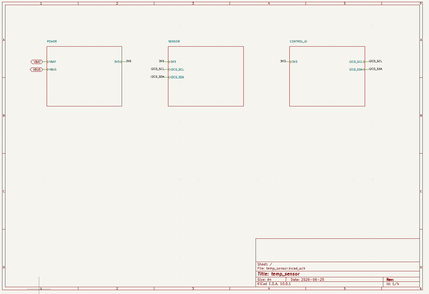
This guide uses the temperature humidity sensor KiCad project as the running example. The original prompt asked for a home temperature and humidity sensor powered by a battery, charged by Type-C, and shown on a small screen. SpeedUp generated a reviewable KiCad project with hierarchical sheets for power, sensor, and control/display blocks, plus a BOM and local libraries.
That structure is useful because it separates the review into manageable engineering questions. The top-level sheet shows whether the major nets are sensible. The power sheet answers how the battery, USB-C input, charger, and regulator interact. The sensor sheet answers how the environmental sensor connects and where it should physically live. The control/display sheet answers how the MCU and screen share the bus and power rail.
Power Path Review
For a battery powered sensor, review power before reviewing the sensor. If the board cannot charge safely, regulate cleanly, or sleep efficiently, the measurement circuit will not matter much.
Start with the energy sources. USB-C input should not be treated as just a two-pin connector. At minimum, check CC resistor handling, ESD protection, VBUS routing, and whether the circuit expects a simple 5 V source or more advanced USB behavior. In this example, the BOM includes a USB-C connector, 5.1k resistors, USBLC6-2SC6 protection, and a resettable protection part.
Then check the battery charger and the system rail. The BQ24074RGTR charger and TPS63031DSKR buck-boost regulator suggest the design is trying to support a Li-ion battery while maintaining a stable 3.3 V rail. Before production, an engineer should verify charge current settings, battery pack assumptions, input current limits, thermal behavior, inductor selection, capacitor ratings, and load transients when the display turns on.
Sensor Placement And I2C Review
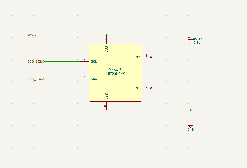
Temperature and humidity accuracy depends on the electrical design and the physical placement. The schematic can show the I2C signals and supply pins, but the PCB and enclosure decide whether the sensor measures room air or heat from the charger, display, regulator, or MCU.
For an I2C environmental sensor, check:
- Pullup values against bus speed, voltage, and sleep current.
- Sensor supply voltage and decoupling.
- I2C address conflicts with the display or other peripherals.
- Whether the sensor should be placed near a vent, away from heat sources, and protected from splash, dust, coating, and residue.
- Whether the firmware needs calibration, filtering, or measurement timing to avoid self-heating effects.
The generated BOM includes a useful note for CHT20MEMS: place it near an enclosure vent, thermally isolate it from charger, regulator, display, and processor heat, and keep the sensing aperture free of coating or residue. That is exactly the kind of generated note worth preserving during review.
Display And Low-Power Behavior
A display makes a sensor product easier to use, but it also changes the power budget. An always-on OLED can dominate battery life, especially in a small home sensor. The schematic review should therefore ask whether the display is always powered, whether it can be dimmed or duty-cycled, and whether the MCU can sleep while the display is off.
In the example project, the control/display sheet includes an ATTINY816-MNR controller and an HS91L02W2C01 OLED display. Before layout, review the display connector, I2C or control signal assumptions, pullups, reset behavior, and firmware states. If the product goal is long battery life, the review should add current measurements and firmware sleep targets to the next design pass.
BOM Review
| BOM area | Example parts in this project | Review before production |
|---|---|---|
| Charging and protection | BQ24074RGTR, USBLC6-2SC6, USB-C connector, fuse/protection device |
Confirm charging profile, current limits, ESD strategy, and connector footprint. |
| Regulation | TPS63031DSKR, inductor, 10 uF and 0.1 uF capacitors |
Check efficiency, load range, stability, capacitor voltage rating, and layout requirements. |
| Control | ATTINY816-MNR |
Confirm firmware capacity, programming/debug path, sleep current, and pin assignments. |
| Sensing | CHT20MEMS |
Confirm address, accuracy, placement, venting, and enclosure interaction. |
| Display | HS91L02W2C01 OLED |
Confirm current draw, interface, connector, refresh behavior, and power gating. |
This is where generated projects become most useful as a review starting point. The BOM gives a concrete list to inspect, not just a vague architecture. It also exposes what is still incomplete: generic passive values may need more review, sourcing alternates may be needed, and datasheet-driven layout rules still need to be checked.
Common Mistakes
- Treating USB-C as a simple power jack without checking CC resistors, ESD protection, and input limits.
- Choosing a regulator without validating efficiency at the product's normal sleep and active currents.
- Placing a temperature sensor near a charger, regulator, MCU, display, or sealed plastic wall.
- Leaving I2C pullups too strong for a low-power device or too weak for reliable communication.
- Reviewing the schematic without checking BOM availability, package names, and footprints.
- Assuming a generated KiCad project is production-ready before electrical, layout, firmware, and enclosure review.
How SpeedUp Fits
SpeedUp can turn a compact product prompt into a first engineering draft with a block diagram, KiCad schematic hierarchy, BOM, and project files. That gives engineers something concrete to review much earlier: power architecture, subsystem boundaries, part choices, and missing validation work become visible instead of staying abstract.
The important boundary is that generated hardware is still a draft. Use it to accelerate exploration, documentation, and the first review pass. Then validate the schematic, footprints, layout constraints, firmware assumptions, sourcing, safety, and measurement performance before treating it as a production design.
Related Project Examples
- Temperature humidity sensor KiCad project – the full project example used in this guide.
- Magnetic AI label microphone KiCad project – another generated hardware example with power, audio, BLE, and storage review points.
- ESP32 e-ink MQTT display KiCad project – a connected display project with interface, power, and firmware assumptions to review.
- Review an AI-generated KiCad schematic before layout, sourcing, or release.
FAQ
What should I check first in a battery powered sensor circuit?
Start with the power path: battery connector, charger, USB input, protection, regulator, and system rail. Power choices affect every later decision, including sensor accuracy, display behavior, firmware sleep modes, and battery life.
Is an I2C temperature humidity sensor schematic enough for production?
No. The schematic is only one part of the design. You still need to validate placement, enclosure airflow, thermal isolation, pullup values, firmware timing, calibration, BOM availability, footprint accuracy, and PCB layout.
Should a small sensor use a display?
It depends on the product goal. A display improves local usability, but it can significantly increase power draw. For a long-life battery product, review whether the display can be dimmed, duty-cycled, or fully powered down.
Can AI generate a KiCad schematic for a sensor product?
AI can generate a useful first draft with a block diagram, schematic sheets, BOM, and part choices. Engineers should still review and validate the design before layout, manufacturing, or deployment.
Start Your Battery Sensor Project
Turn your low-power sensor requirements into a structured, editable KiCad first draft.
Use SpeedUp to turn the product requirements into structured schematic sheets and an editable KiCad first draft for engineering review. Create a free account to begin.
Comments
No comments yet.
Leave a Reply