
Quick Answer
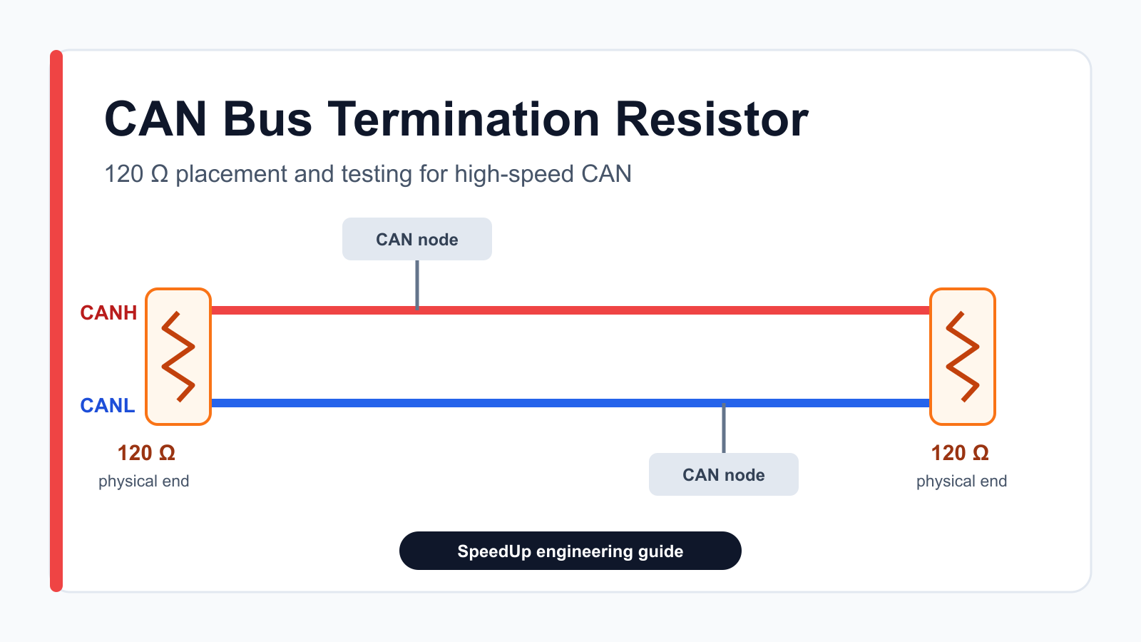
A high-speed CAN bus normally uses one 120 Ω termination resistor across CANH and CANL at each physical end of the cable trunk. Intermediate nodes are normally left unterminated and connected with short stubs. The two endpoint resistors appear in parallel to the transceivers, producing a nominal 60 Ω differential load across the complete bus.
Place termination according to the physical network, not according to which controller is logically first or last. If a board may be installed at either an endpoint or a middle position, use a documented DNP, jumper-selectable, or properly designed electronic termination option. With the network de-energized and active interfaces isolated, a resistance measurement between CANH and CANL should be about 60 Ω when both 120 Ω endpoint terminations are present. That static test can find missing or extra terminators, but it cannot prove that stub length, cable impedance, bit rate, protection parts, or PCB layout are correct.
Scope: this guide addresses high-speed CAN and CAN FD physical networks based on the ISO 11898-2 style of differential twisted-pair wiring. Do not apply the same termination rules blindly to every low-speed, fault-tolerant, single-wire, or application-specific CAN physical layer.
Why CAN Bus Termination Matters
A CAN cable behaves as a transmission line when signal-edge travel time is significant relative to the bit timing. An impedance discontinuity at an unterminated cable end reflects part of the signal back toward the transmitter. The result can be ringing, delayed threshold crossings, extra edges, intermittent errors, or a network that works on a short bench harness but fails after the cable, node count, temperature, or data rate changes.
The termination resistance is chosen to match the cable’s characteristic impedance. For conventional high-speed CAN, the common target is 120 Ω. The CAN in Automation high-speed transmission guidance recommends a line topology terminated at both ends with 120 Ω resistors matching the cable. Texas Instruments shows the same standard and split termination arrangements in its CAN physical-layer application report.
Termination is also a load. Two 120 Ω resistors in parallel produce 60 Ω across CANH and CANL. Adding a third 120 Ω termination lowers the equivalent resistance to 40 Ω, while four lower it to 30 Ω. That extra load can reduce the dominant differential voltage and push the transceiver outside the conditions under which its output performance is specified. More termination is not safer.
CAN Bus Termination Checklist
| Review area | What to check | Why it matters |
|---|---|---|
| Physical layer | Confirm that the network is high-speed CAN or CAN FD and identify the governing system profile. | Other CAN physical layers can use different wiring and termination. |
| Cable impedance | Verify the cable or harness characteristic impedance and connector assumptions. | Termination should match the transmission line; 120 Ω is common, not a magic value detached from the cable. |
| Topology | Identify the two physical ends of the trunk and every stub. | Passive star branches and long stubs introduce additional reflection points. |
| Endpoint resistors | Fit one 120 Ω differential termination at each physical end. | The complete bus then presents a nominal 60 Ω differential load. |
| Intermediate nodes | Normally leave them unterminated and keep their stubs short. | Termination at every node overloads the bus and does not remove stub reflections. |
| Removable nodes | Ensure removing an endpoint device does not accidentally remove required cable termination. | A network may become unterminated during service or reconfiguration. |
| Termination type | Choose standard, split, jumper-selectable, or electronic termination deliberately. | Each option has BOM, EMC, reliability, and configuration consequences. |
| Power rating | Check resistor voltage, pulse, temperature, and fault dissipation against the transceiver and system. | Cable shorts to higher-voltage rails can exceed normal communication dissipation. |
| Test access | Provide safe access to CANH, CANL, and ground at representative network points. | Resistance and oscilloscope checks should not require improvised probing. |
| Documentation | Record which installation positions require termination and the default assembly state. | A correct schematic can still be assembled or configured incorrectly. |
Designing a CAN node or multi-node bus?
Describe the controller, transceiver, network role, cable, connector, protection environment, and termination strategy. Create a free account to start a reviewable, editable KiCad first draft.
CAN Termination Resistor Schematic Patterns
A CAN termination resistor schematic should make the board’s physical role obvious before layout or assembly. Show the terminator between the named CAN_H and CAN_L nets, then document whether it is fitted, not fitted, or selectable by default. The correct choice follows the two physical ends of the cable, not the number of nodes on the network.
| Board role | Schematic implementation | Default assembly state | Evidence a reviewer should see |
|---|---|---|---|
| Dedicated endpoint | One 120 Ω resistor, usually named RTERM, directly between CAN_H and CAN_L | Fitted | Named bus nets, resistor value, and an endpoint note |
| Endpoint or intermediate node | 120 Ω resistor controlled by a solder jumper, removable shunt, or explicit DNP option | Documented as fitted or open for the intended product configuration | Jumper state, BOM/DNP state, and an assembly note that agrees with the schematic |
| Split-termination endpoint | Two approximately 60 Ω resistors in series across CAN_H and CAN_L, with the midpoint capacitor chosen from transceiver guidance | Fitted only when split termination is part of the EMC strategy | Matched resistor values, midpoint capacitor value, return path, and supporting transceiver guidance |
| Software-selectable endpoint | A reviewed switch topology that inserts or removes the termination network | Safe and defined during reset and while the board is unpowered | Switch ratings, control default, leakage path, and failure-state behavior |
For a reusable node, a selectable 120 Ω footprint is usually easier to review than an unexplained fixed resistor. The schematic, BOM, assembly drawing, and setup instructions should all state the same default so a middle node is not accidentally shipped with termination enabled.
Where to Place the Two 120 Ω Resistors
Place the resistors at the two farthest physical ends of the main CAN trunk. They can be inside the endpoint nodes or in dedicated cable terminators. What matters is that the transmission line actually ends at each resistor and that both terminations remain present in every supported configuration.

The logical order of CAN identifiers, arbitration priority, or software roles does not determine termination. A gateway, motor controller, sensor, or diagnostic tool needs termination only when its connector is at a physical end of the active network. A node located in the middle of the harness normally does not need 120 Ω even if it is the application master.
Stub length deserves its own timing review. There is no single safe stub length for every CAN or CAN FD design because the limit depends on edge rate, arbitration and data bit rates, cable delay, transceiver timing, node loading, connectors, and topology. Keep stubs as short as practicable and validate the actual network rather than copying a universal number from a forum.
Standard vs Split CAN Termination
Standard termination is one resistor, typically 120 Ω, directly between CANH and CANL at an endpoint. Split termination replaces it with two matched resistors, typically 60 Ω each, connected in series between CANH and CANL. Their midpoint connects to ground through a capacitor. The differential DC resistance remains about 120 Ω at that endpoint.

Split termination can stabilize and filter common-mode voltage and improve emissions behavior. It does not compensate for an incorrect topology or missing endpoint. The TI TCAN1043-Q1 datasheet shows two 60 Ω resistors and notes a typical 4.7 nF split capacitor, with values up to 100 nF in that device’s guidance. Treat those figures as vendor guidance for a particular implementation, not as universal values for every transceiver, cable, ground strategy, or EMC target.
Match the two split resistors closely, place the network as the transceiver or system reference recommends, and evaluate the capacitor return path. The midpoint is a common-mode filter node, not permission to connect noisy chassis, digital, or isolated grounds together without reviewing the isolation and EMC architecture.
Fixed, Jumper-Selectable, and Electronic Termination
Fixed termination is the most predictable choice when a product is always installed at one end of the bus. If the same PCB can appear at an endpoint or in the middle, adding a DNP resistor footprint or jumper-selectable termination can reduce assembly variants. The configuration must be visible in the schematic, assembly documentation, enclosure labeling, and test plan.
A solder jumper is appropriate only when infrequent configuration is acceptable. Review the SpeedUp guide to solder jumpers in KiCad schematics for labeling, default state, assembly access, and documentation considerations. A removable shunt or switch is easier to service but introduces its own connector, contact, and user-error risks.
Software-controlled termination is possible when identical nodes must be dynamically assigned as endpoints. It is not simply a GPIO placed in series with a random analog switch. Switch on-resistance, parasitic capacitance, fault voltage, unpowered behavior, isolation, default state, and failure mode all matter. Texas Instruments’ TIDA-01238 selectable CAN termination reference design and isolated CAN design guidance show reviewed approaches and explain why only the two farthest nodes should enable their 120 Ω networks.
How to Test CAN Bus Termination Resistance
Never use an ohmmeter on an energized or actively switching bus. Follow the equipment’s safe shutdown procedure, remove power from the network, discharge stored energy where applicable, and isolate or disconnect active CAN interfaces as the system documentation requires. Then measure resistance directly between CANH and CANL from an accessible connector. The TI CAN EVM user’s guide uses two 120 Ω resistors in parallel to represent the standard 60 Ω bus load for electrical measurements.

| Approximate reading | Likely interpretation | Next check |
|---|---|---|
| About 60 Ω | Two 120 Ω endpoint networks are probably present. | Confirm their physical locations and then test the active waveform. |
| About 120 Ω | Only one endpoint termination may be enabled or connected. | Inspect the opposite endpoint, cable, connector, jumper, and assembly state. |
| About 40 Ω | Three 120 Ω terminations may be present in parallel. | Find the unintended termination; do not assume the lower resistance is beneficial. |
| Very high or open | No complete differential termination path is visible from the measurement point. | Check both endpoints, cable continuity, connectors, and measurement isolation. |
| Unexpected or unstable | The network may still be powered, connected electronics may influence the reading, or protection/switching circuits may be involved. | Stop and verify the safe test state and schematic before drawing a conclusion. |
A correct 60 Ω reading does not prove the network is healthy. It cannot reveal an endpoint resistor located at the end of a long branch instead of the trunk, excessive stub length, a poor cable, connector discontinuity, marginal transceiver timing, asymmetric protection capacitance, or ringing at the selected bit rate. Use an oscilloscope or appropriate CAN analysis equipment to inspect CANH, CANL, and differential behavior at representative near and far nodes while the final harness and node population are operating.
Example From a SpeedUp CAN Schematic Review
The existing SN65HVD230 CAN bus schematic checklist treats termination as a system decision rather than a resistor copied from a breakout board. A reviewer first asks whether the board is always an endpoint, sometimes a middle node, or a diagnostic adapter. That answer determines whether the schematic should show a fixed 120 Ω resistor, a split network, a selectable option, or no fitted termination.
For an SN65HVD230 or another CAN transceiver, the review must continue beyond termination. Check the transceiver supply and decoupling, MCU TXD/RXD connections, standby or slope-control behavior, CANH/CANL connector mapping, protection, common-mode and fault limits, test points, and whether the selected device supports the required CAN or CAN FD application. The termination guide and the transceiver checklist have different primary search intents, but together they describe a more complete interface review.
CAN Node Schematic Decision Table
| Decision | Endpoint implementation | Intermediate-node implementation |
|---|---|---|
| Termination state | 120 Ω fitted, or the termination option enabled | Termination omitted, DNP, or the option left open |
| Connection to the trunk | Placed at the physical cable end | Connected with the shortest practical stub for the data rate and network timing |
| Protection and transceiver | Selected for the bus voltage, fault, ESD, and common-mode requirements | The same electrical checks still apply; removing termination does not remove the need for protection |
| Documentation | Assembly notes identify the board as an endpoint and state the enabled default | Assembly notes state that termination is disabled unless the board becomes a cable endpoint |
| Bench resistance check | A fully assembled, unpowered network with both endpoints connected should measure about 60 Ω between CAN_H and CAN_L | The node alone should not add another 120 Ω path across the bus |
This decision is a system-level property. Two identical boards may need different termination states when one is installed at a cable end and the other is installed in the middle of the same network.
Common CAN Termination Mistakes
- Placing 120 Ω on every CAN transceiver because every reference schematic contains an optional footprint.
- Choosing termination from the logical controller hierarchy instead of the physical cable ends.
- Removing an endpoint device and unintentionally removing one of the two required terminators.
- Using a passive star and assuming extra termination resistors will eliminate every branch reflection.
- Copying a split capacitor value without checking the transceiver data sheet, EMC target, grounding, and isolation architecture.
- Ignoring resistor voltage and power behavior during cable-to-supply or cable-to-ground faults.
- Measuring resistance while the network is energized or data is active.
- Treating a 60 Ω multimeter reading as proof that the active CAN waveform and CAN FD timing are valid.
- Moving to layout without documenting default jumper state, DNP parts, connector role, and endpoint assumptions.
How SpeedUp Fits
SpeedUp can turn a product requirement into a structured KiCad schematic draft that shows the MCU or CAN controller, transceiver, CANH/CANL connector, candidate protection, termination option, control pins, test points, and design notes in one reviewable interface block. A useful prompt should state the expected network position, cable or connector, CAN or CAN FD rate, supply domains, isolation needs, protection environment, and whether termination must be fixed or configurable.
The generated result is a first engineering draft, not a production-ready reference design. Engineers still verify the physical-layer standard, transceiver data sheet, topology, cable, bit timing, termination and protection networks, resistor ratings, isolation, PCB layout, firmware configuration, sourcing, safety, compliance, manufacturing, and hardware test results. Use the broader schematic review checklist before PCB layout to document those decisions.
Related SpeedUp Guides
- What to check before using an AI-generated KiCad schematic for PCB layout — downstream review for footprints, layout constraints, validation gaps, and release readiness.
FAQ
Does a CAN bus need a termination resistor?
A conventional high-speed CAN or CAN FD line normally needs termination at both physical ends. Confirm the actual physical-layer standard and system profile because not every CAN implementation uses the same network.
Why does CAN bus use 120 Ω resistors?
The resistance is selected to match the characteristic impedance of the commonly specified high-speed CAN twisted-pair cable. Matching the cable ends reduces reflections. The value is about the transmission line, not a pull-up or pull-down requirement of the logic pins.
What Are CAN_H and CAN_L?
CAN_H and CAN_L are the two conductors of the differential high-speed CAN physical layer. During a dominant bit, CAN_H rises and CAN_L falls relative to their recessive common-mode level, and the receiver responds to the voltage difference between them. Termination connects between CAN_H and CAN_L at the two physical ends of the bus—not from either signal to ground. Exact voltage, common-mode, and fault limits depend on the selected transceiver and CAN physical-layer standard.
How many 120 Ω termination resistors should a CAN bus have?
A standard linear high-speed CAN bus normally has two: one at each physical end of the trunk. Intermediate nodes normally do not fit 120 Ω termination.
What resistance should I measure between CANH and CANL?
With the network safely de-energized and active interfaces isolated, two 120 Ω endpoint resistors in parallel should measure approximately 60 Ω, allowing for tolerance and other connected circuitry. About 120 Ω often suggests one missing endpoint, while about 40 Ω can suggest three parallel 120 Ω terminations.
Can the termination resistor be placed on the PCB?
Yes, if that PCB is genuinely at the physical end of the active cable. If the board can be removed or used in the middle of the network, make termination selectable or place it in the cable so that the required endpoint terminations remain present.
Is split termination always better than one 120 Ω resistor?
Not automatically. Split termination can improve common-mode stabilization and emissions, but it adds components and a grounding-dependent capacitor path. Use the transceiver vendor’s guidance and validate the final network and EMC behavior.
Can a 60 Ω resistance test confirm CAN FD signal integrity?
No. It confirms only the approximate static differential resistance seen from the measurement point. CAN FD performance still depends on data-phase timing, cable and connector impedance, stub length, transceivers, protection components, layout, node count, and active waveform quality.
Start Your CAN Bus Project
Turn your CAN topology and termination decisions into an editable KiCad first draft.
Use SpeedUp to turn the product requirements into structured schematic sheets and an editable KiCad first draft for engineering review. Create a free account to begin.
Comments
No comments yet.
Leave a Reply