
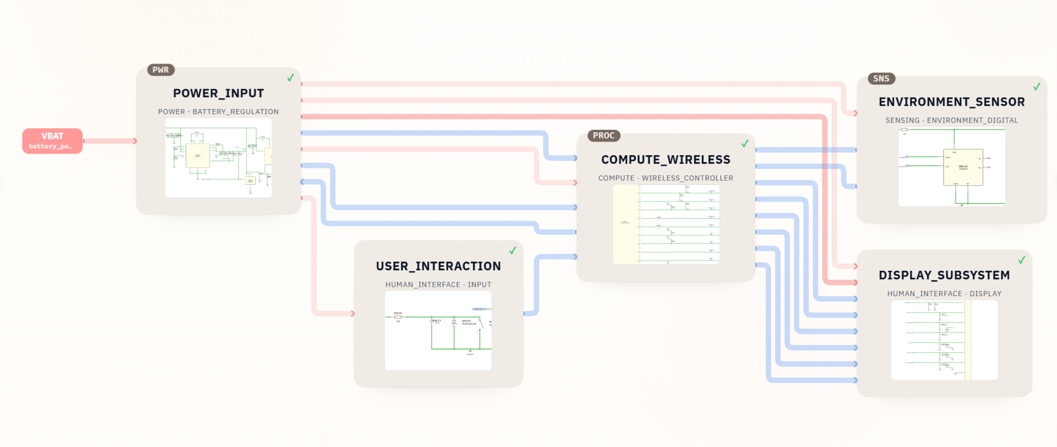
This project shows how SpeedUp can turn a device idea into a reviewable ESP32 KiCad schematic package. The generated desktop robot project focuses on controller electronics: battery input and power regulation, an ESP32-WROOM-32E wireless controller, an internal display connector, a temperature and humidity sensor, and a simple user-input path.
This is a first engineering draft for review, not a production-ready reference design. The package provides schematic sheets, symbol and footprint libraries, and a BOM, but it does not include a routed PCB layout, firmware, motor drivers, enclosure files, or production validation data.
Project Summary
| Field | Details |
|---|---|
| Project | Desktop robot controller electronics |
| Input | Natural-language prompt, but the exact prompt text was not included in the source package |
| Output | KiCad schematic project |
| Key modules | POWER_INPUT, COMPUTE_WIRELESS, DISPLAY_SUBSYSTEM, ENVIRONMENT_SENSOR, USER_INTERACTION |
| Included files | KiCad project and schematic files, 5 module sheets, symbol libraries, footprint libraries, CSV/XLSX BOM, downloadable ZIP |
| Status | First engineering draft for review |
The Prompt
The source ZIP and neighboring asset folder did not include the original prompt text or a prompt screenshot. Because of that, the article does not quote a prompt verbatim. Instead, it uses the generated KiCad project name, module sheets, block diagram, schematic screenshots, and BOM as the source of truth.
For a production blog batch, the prompt screenshot should be added before publishing so readers can see the exact natural-language request that produced the engineering files.
What SpeedUp Generated
SpeedUp generated a structured KiCad schematic project for a desktop robot-style embedded device. The package includes:
desktop_robot.kicad_proanddesktop_robot.kicad_sch- Module sheets for power input, wireless compute, display, environment sensing, and user interaction
- Symbol libraries for device parts, power, sensors, connectors, power management, circuit protection, and IoT communication modules
- A footprint library with footprints for the ESP32-WROOM-32E module, FPC connector, regulator packages, passives, switch, fuse, and protection parts
- A CSV and XLSX BOM with 39 line items and 75 placed quantities
- Supporting screenshots that show the architecture, top-level sheet, power circuit, and ESP32/control wiring
Want to create an ESP32 robot controller like this?
Describe your own ESP32 desktop robot controller requirements and create a free account to start a reviewable engineering draft.
Project Architecture
The generated design is organized into five reviewable modules:
POWER_INPUT: acceptsVBAT, adds fuse/protection elements, generatesSYS_3V3, controlsVDISP_5V, and exposes battery and power-good signals.COMPUTE_WIRELESS: centers on an ESP32-WROOM-32E-N8 module and routes display, I2C, power-status, and user-event signals.DISPLAY_SUBSYSTEM: connects an internal SPI display through a 12-position 0.5 mm FPC connector with display power, reset, command/data, chip-select, MOSI, SCK, and backlight PWM signals.ENVIRONMENT_SENSOR: adds an HTU21D humidity and temperature sensor on the I2C bus.USER_INTERACTION: provides a momentary pushbutton input path with ESD protection and debounce/noise filtering.
The theme-rendered featured image shows these modules as an architecture map, with power and signal paths flowing between the power input, ESP32 controller, display subsystem, environment sensor, and user interaction block.
ESP32 KiCad Schematic Output
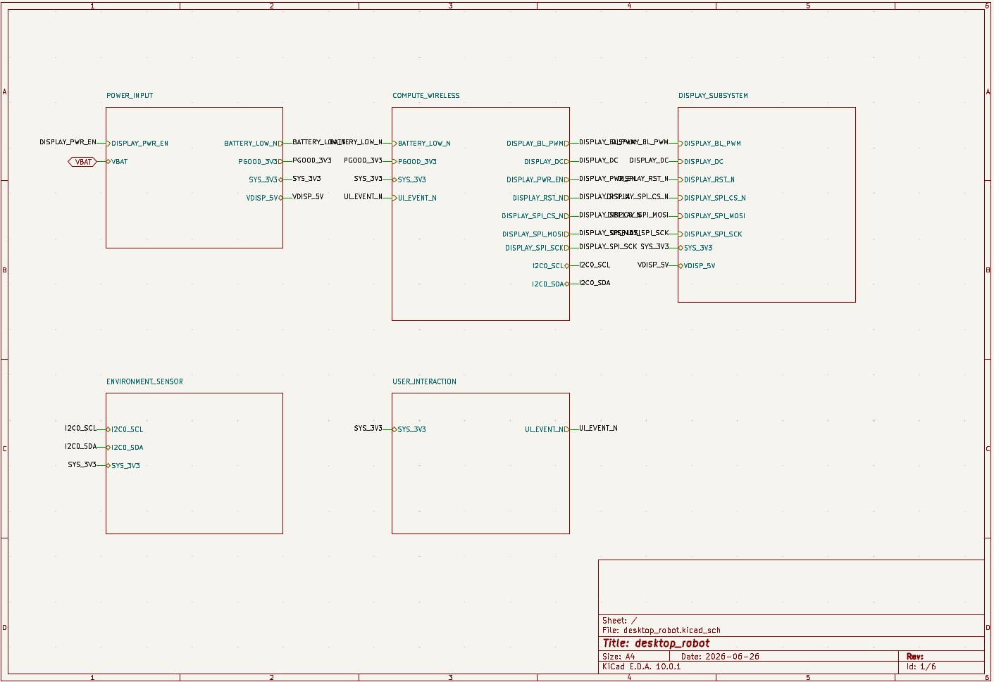
The top-level sheet is useful because it makes the generated project reviewable before digging into component details. A hardware engineer can quickly see that the project is not a complete robot drivetrain design; it is a controller-and-interface electronics draft for a desktop robot-style product.
The downloadable package includes the main KiCad project, module-level schematic files, local symbol libraries, local footprint libraries, and BOM files. No .kicad_pcb board layout file was present in the source package, so layout, design-rule checks, and manufacturing outputs still need to be created.
Power Input and Display Rail Control
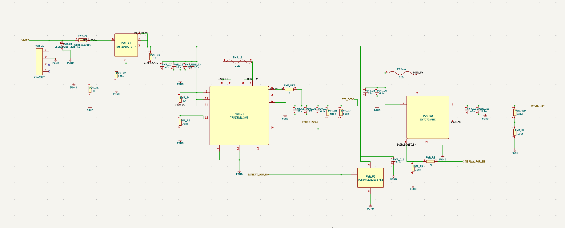
The POWER_INPUT sheet is the most important review area in this project. It includes battery input protection, a fuse, ESD protection, a high-side/protection MOSFET path, a TPS63021DSJT regulator for SYS_3V3, a SY7072AABC stage for the display rail, and a TC54VN3002ECB713 voltage detector for battery-low signaling.
Before layout, this subsystem should be checked for regulator operating range, inductor and capacitor selection, transient behavior during display wake-up, power-good timing, battery-low thresholds, thermal behavior, and grounding. The display rail control path also needs firmware assumptions documented, because DISPLAY_PWR_EN changes the power state of the display subsystem.
ESP32 Wireless Control and Display Interface
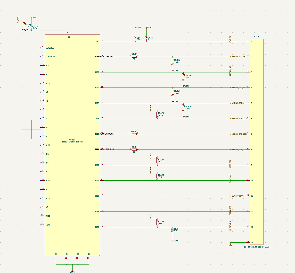
The COMPUTE_WIRELESS module uses the ESP32-WROOM-32E-N8 as the main wireless controller. The BOM notes call out the integrated 2.4 GHz Wi-Fi/Bluetooth antenna and the need to reserve an antenna keepout while keeping display SPI and regulator switching loops away from the RF area.
That makes this sheet more than a pin list. It captures practical review items for a real board: RF keepout, SPI trace routing to the display connector, I2C pull-up and bus behavior, reset/enable behavior, display backlight PWM, and the relationship between PGOOD_3V3, BATTERY_LOW_N, and firmware power-state decisions.
Sensor, Display, and User Input Details
The generated display subsystem uses an HC-FPC-05-20-12RLTAG connector. The BOM describes it as a 12-position, 0.5 mm flip-lock FPC connector for an internal SPI display assembly, with pins assigned for VDISP_5V, SYS_3V3, SCK, MOSI, CS_N, DC, RST_N, BL_PWM, and grounds.
The environment sensor is an HTU21D temperature and humidity sensor on I2C address 0x40. The BOM includes useful placement notes: expose the sensor to ambient air through enclosure venting, keep it away from the display, regulator, radio, and processor heat, and do not conformal-coat the sensing opening.
The user interaction path is simple but still reviewable. It includes a momentary pushbutton, a single-line bidirectional ESD clamp, and RC filtering for the UI_EVENT_N signal. That is enough for a first input path, but the final behavior still depends on firmware debounce logic, enclosure button mechanics, and ESD test requirements.
BOM Preview
The generated BOM includes 39 line items and 75 placed quantities. Representative parts include:
MCU_U1: ESP32-WROOM-32E-N8 wireless moduleDSP_J1: HC-FPC-05-20-12RLTAG display connectorENV_U1: HTU21D temperature and humidity sensorPWR_U1: TPS63021DSJT regulatorPWR_U2: SY7072AABC display rail power stagePWR_U3: TC54VN3002ECB713 voltage detectorPWR_Q1: DMP2010UFV-7 MOSFETPWR_F1: K1812L300DR fuseUIN_S1: TD-1185SA-2.5H-160 momentary pushbuttonUIN_D1: PESD5V0S1BB ESD clamp
This gives engineers a starting point for component review, sourcing checks, footprint validation, cost estimation, and substitution planning. It should not be treated as a final approved BOM until the schematic, PCB layout, thermal behavior, assembly constraints, and supply-chain status have been reviewed.
What Still Needs Human Review
This desktop robot project is a useful first draft, but several production-critical pieces are still missing or unresolved:
- Confirm whether the product needs motors, servos, speakers, microphones, LEDs, battery charging, USB, or other subsystems not present in this package. If a later revision adds a relay, solenoid, or brushed-motor stage, review the flyback diode and clamp path as part of the motor-driver schematic rather than treating the controller output as a direct inductive-load connection.
- Add or review the PCB layout, including regulator loops, ESP32 antenna keepout, FPC connector placement, sensor venting, and ESD return paths.
- Validate regulator selection, inductor saturation current, capacitor voltage rating, display inrush behavior, and power sequencing.
- Check ESP32 boot strapping, reset behavior, GPIO assignments, firmware debounce, display initialization, I2C pull-ups, and low-battery behavior.
- Review the HTU21D placement against enclosure heat sources and airflow assumptions.
- Verify every footprint and land pattern against current manufacturer recommendations.
- Add design-rule checks, ERC/DRC reports, thermal checks, assembly drawings, firmware, enclosure constraints, and compliance planning before production.
Related SpeedUp Projects and Guides
- KiCad Schematic Generator: Product Prompt to Editable KiCad Project
- How to Review AI-Generated KiCad Schematics Before PCB Layout
- Temperature and Humidity Sensor KiCad Project
FAQ
Is this desktop robot design production ready?
No. It is a first engineering draft intended for review and iteration. The project includes useful schematic, BOM, symbol, and footprint evidence, but it still needs PCB layout, firmware, mechanical integration, validation, and production review.
Does the package include a complete robot drivetrain?
No. The generated project focuses on controller electronics, display, environment sensing, user input, and power rails. It does not include motor drivers, actuator control, wheel or servo interfaces, chassis files, or motion firmware.
What files are included in the generated project?
The package includes a KiCad project file, a top-level schematic, module schematic sheets, symbol libraries, footprint libraries, and BOM files in CSV and XLSX formats. It also includes supporting screenshots outside the source ZIP that can be used to explain the generated architecture and schematic output.
Can this be opened in KiCad?
Yes, the package includes desktop_robot.kicad_pro and .kicad_sch files intended for KiCad review. The source package does not include a routed .kicad_pcb file, so engineers should treat it as a schematic-stage project.
What should engineers review first?
Start with the power input and regulator behavior, ESP32 RF placement constraints, display connector pinout, HTU21D sensor placement, and BOM/footprint validation. Then add missing product requirements such as charging, motors, firmware, enclosure constraints, and compliance assumptions.
Can I generate a similar project from my own prompt?
Yes. SpeedUp is designed to turn a natural-language device idea into structured engineering artifacts that can be reviewed, refined, and extended by engineers.
Download the Desktop Robot KiCad Project
Use this desktop robot ZIP as a review starting point for the generated KiCad schematic project. The package includes the KiCad project, schematic sheets, symbol libraries, footprint libraries, and BOM files; add PCB layout, firmware, mechanical design, motor or actuator electronics if required, validation reports, and manufacturing outputs before treating it as a complete engineering handoff.
Create Your Own ESP32 Robot Project
Turn your own ESP32 desktop robot controller brief into reviewable engineering artifacts.
Use SpeedUp to generate structured schematic sheets and an editable KiCad project for engineering review. Create a free account to begin.
Comments
No comments yet.
Leave a Reply