
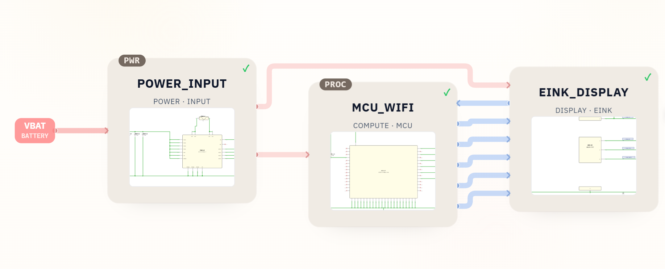
SpeedUp turned a short product prompt into an editable KiCad project for a small ESP32-based e-ink message card. The download now includes the top-level and module schematics, local symbol and footprint libraries, a BOM, and an unrouted PCB draft—not only exported screenshots.
This is a first engineering draft for review, not a production-ready reference design. It gives hardware engineers and embedded developers concrete source files for reviewing the architecture, power path, ESP32-C3 connections, display interface, footprints, and board placement before routing, firmware development, validation, and manufacturing.
Project Summary
| Field | Details |
|---|---|
| Project | Small ESP32 e-ink card for receiving and displaying messages |
| Input | Natural-language product prompt |
| Output | Editable KiCad project with hierarchical schematics and an unrouted PCB draft |
| Key modules | POWER_INPUT, MCU_WIFI, EINK_DISPLAY |
| Included files | KiCad project, top-level and module schematics, PCB draft, symbol libraries, footprint library, CSV/XLSX BOM, prompt, and block diagram |
| Not included | Routed copper, firmware, fabrication outputs, enclosure files, validation data, and production sign-off |
| Status | First engineering draft for review |
The Prompt
The project starts with this product request:
Design a small card that receives and displays messages, using an e-ink screen, based on an ESP32 + Wi-Fi + MQTT solution
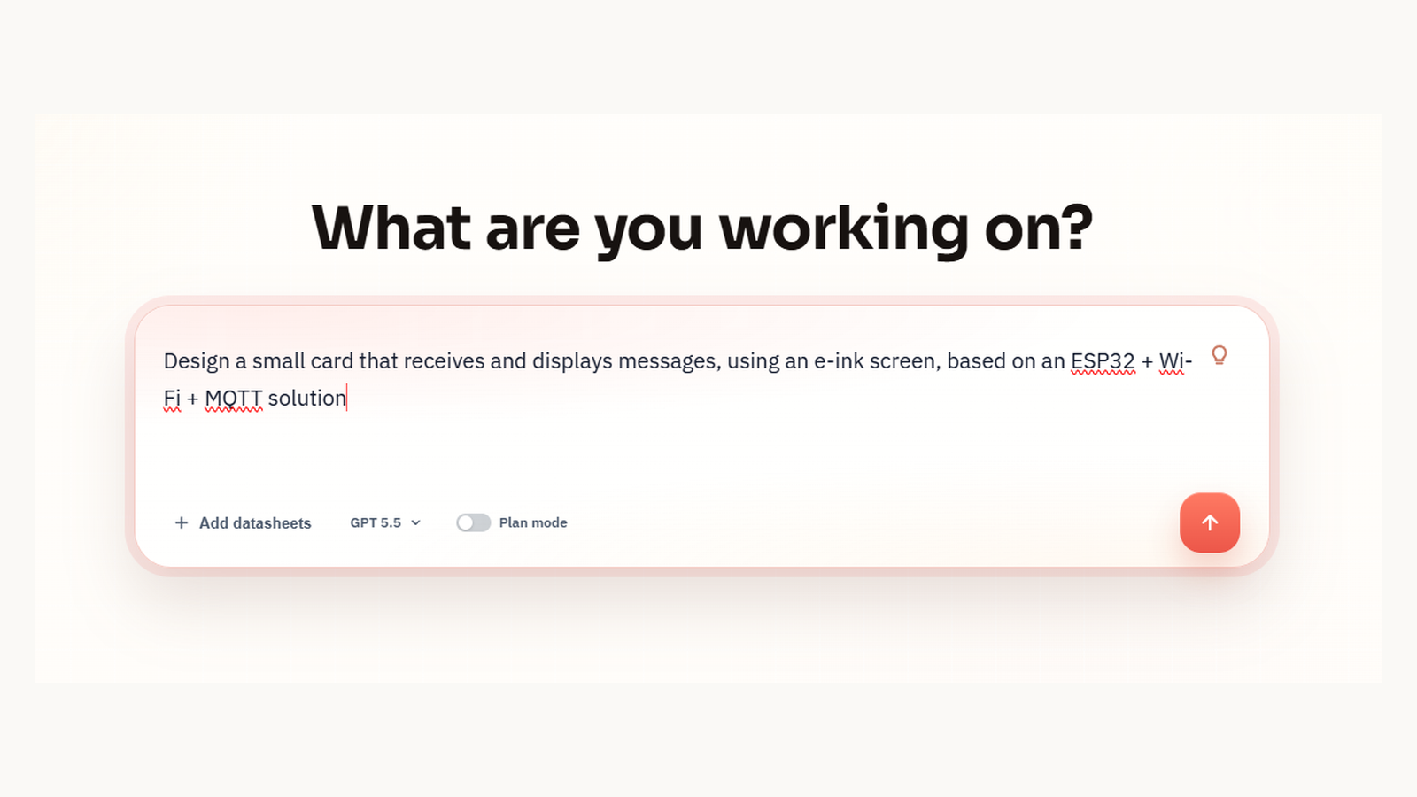
This prompt defines the product behavior: receive messages over Wi-Fi/MQTT and show them on an e-ink screen.
What SpeedUp Generated
From that prompt, SpeedUp generated a structured hardware project with:
elink_card.kicad_proand a top-levelelink_card.kicad_sch- Three hierarchical sheets:
POWER_INPUT,MCU_WIFI, andEINK_DISPLAY elink_card.kicad_pcbwith 25 placed footprints and the project nets, but no routed copper, vias, or zones- Seven local symbol libraries and a local footprint library with 12
.kicad_modfiles - CSV and XLSX BOM files with 15 line items and 25 placed quantities
- A block diagram, prompt evidence, and subsystem schematic images
The package is editable in KiCad and gives reviewers the actual project structure behind the images shown in this article. Its PCB file is still a placement-stage draft, so it should not be described as a completed layout.
Want to create an ESP32 e-ink product?
Describe your own ESP32 e-ink MQTT display requirements and create a free account to start a reviewable engineering draft.
Project Architecture
The featured block diagram organizes the design into three reviewable modules:
POWER_INPUT: acceptsVBAT, adds input protection and bulk capacitance, and generates the3V3rail used by the cardMCU_WIFI: uses an ESP32-C3 module as the Wi-Fi/MQTT controller and exposes the e-ink control signalsEINK_DISPLAY: connects the display connector, protection components, and SPI-style e-ink interface signals
This partitioning matches the prompt well. The device is intended as a low-power message endpoint: receive data over Wi-Fi, handle MQTT in firmware, and refresh the e-ink panel when the displayed content changes.
Editable KiCad Source Package
The download includes elink_card.kicad_pro, a top-level hierarchical schematic, the three module sheets, sym-lib-table, fp-lib-table, local symbol libraries, local footprint files, and BOM exports. Opening the project file keeps the relative modules/, symbols/, and libs/ProjectFootprints.pretty/ paths together for continued engineering work.
The included .kicad_pcb is real editable board source, but it is not a routed board. It contains 25 footprints and net assignments without tracks, vias, or copper zones. Treat it as an early placement handoff that still needs board outline, stack-up, routing, antenna keepout, power integrity, clearance, manufacturability, and fabrication review.
Power Input and 3.3 V Rail
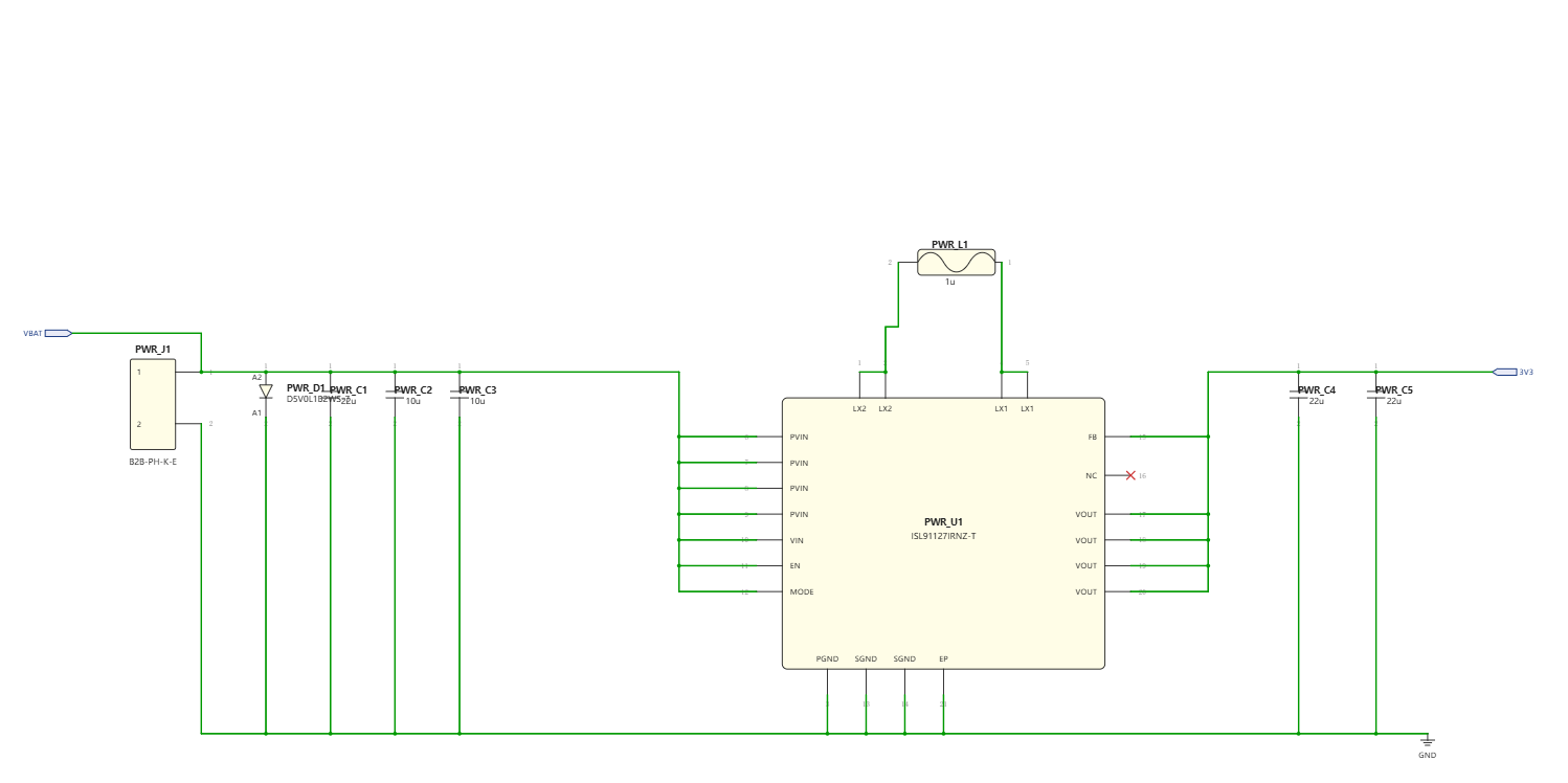
The POWER_INPUT sheet shows battery input, input capacitance, an inductor, output capacitors, and an ISL91127IRNZ-T regulator stage. Wi-Fi transmit current and e-ink refresh events can create short load spikes even when the average power budget is low.
Review should focus on battery range, regulator mode, inductor saturation current, output ripple, quiescent current, ESP32 brownout margin, display refresh current, and the intended sleep and wake behavior.
ESP32 Wi-Fi MCU Section
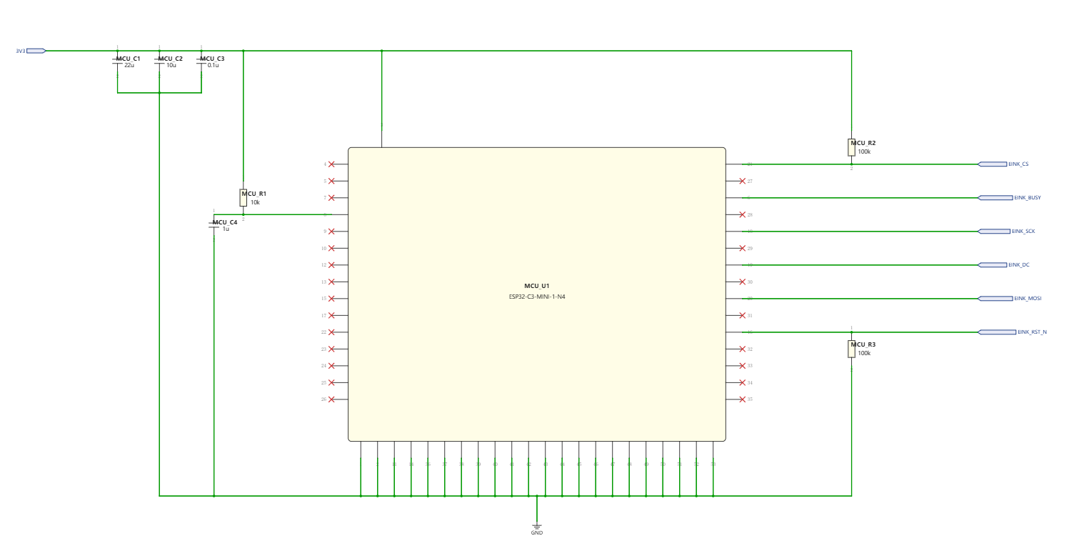
The ESP32-C3 handles Wi-Fi association, MQTT communication, message parsing, and display refresh commands. Before routing, review the boot-strapping pins, reset behavior, programming and debug access, antenna keepout, Wi-Fi current peaks, and every intentionally unused pin.
E-Ink Display Interface
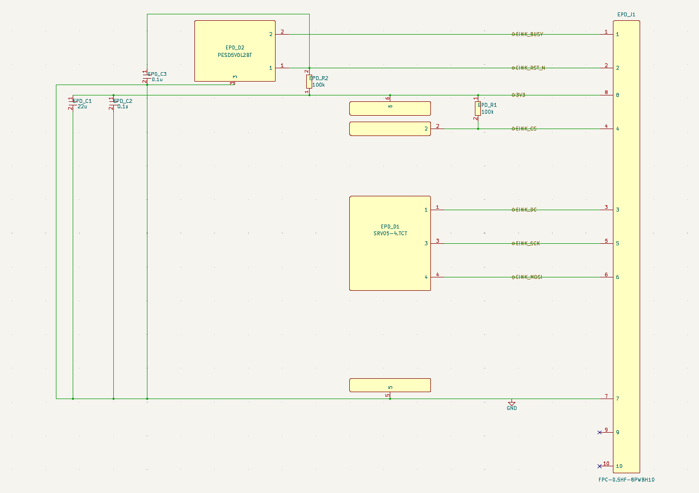
The EINK_DISPLAY sheet includes an eight-position FPC connector and protection components such as PESD5V0L2BT and SRV05-4.TCT. The exact panel still determines the connector pinout, voltage tolerance, waveform timing, refresh current, ESD strategy, and mechanical stack-up.
BOM Preview
The generated package includes BillOfMaterials.csv and BillOfMaterials.xlsx with 15 line items and 25 placed quantities. Representative entries include:
ESP32-C3-MINI-1-N4for Wi-Fi/MQTT controlISL91127IRNZ-Tin the power stagePESD5V0L2BTandSRV05-4.TCTfor interface protectionFPC-0.5HF-8PWBH10for the e-ink panel connection
The BOM is a concrete sourcing starting point, not a validated production list. Manufacturer part numbers, lifecycle status, alternates, pricing, footprint-to-datasheet checks, and supply availability still need review.
What Still Needs Human Review
Before this becomes a production design, review:
- ESP32-C3 boot, reset, programming, debug, and firmware-update paths
- Wi-Fi antenna placement, keepout, enclosure effects, and transmit-current peaks
- MQTT provisioning, broker security, TLS support, credential storage, and reconnect behavior
- E-ink panel choice, connector pinout, waveform timing, refresh current, and image-update behavior
- Battery range, regulator stability, inductor current, ripple, and sleep-mode current
- Footprint and land-pattern accuracy against current component datasheets
- PCB stack-up, board outline, routing, grounding, clearance, thermal behavior, and manufacturing constraints
- Firmware, test coverage, environmental assumptions, compliance needs, and production validation
Related SpeedUp Projects and Guides
- AI Schematic Generator for KiCad Circuit Projects
- Schematic Review Checklist Before PCB Layout
- Desktop Robot ESP32 KiCad Schematic Project
FAQ
Is this design production ready?
No. It is a first engineering draft intended for review and iteration. The package contains editable source, but the board still needs routing, firmware, validation, manufacturing outputs, and production review.
Does the download include editable KiCad source?
Yes. It includes the KiCad project, top-level and module schematics, an unrouted PCB draft, local symbol and footprint libraries, and CSV/XLSX BOM files. The source can be inspected and modified in a compatible KiCad version.
Is the PCB layout complete?
No. The .kicad_pcb file contains 25 placed footprints and net assignments, but no tracks, vias, or copper zones. It is an editable placement-stage draft, not a fabrication-ready layout.
Can this card receive messages over MQTT?
The hardware architecture supports that goal because it uses an ESP32 Wi-Fi module and an e-ink display interface. MQTT behavior depends on firmware, Wi-Fi provisioning, broker configuration, payload format, security, and power-state requirements.
What should engineers check first?
Start with the selected e-ink panel datasheet, connector pinout, ESP32-C3 boot requirements, regulator sizing, antenna constraints, and firmware update path. Those decisions will shape the routing and determine whether the draft can become a reliable product.
Can I generate a similar project from my own prompt?
Yes. SpeedUp is designed to turn a natural-language device idea into structured, editable engineering artifacts that can be reviewed and refined.
Download the ESP32 E-Ink MQTT Display KiCad Project
Use this ZIP as a review starting point for the generated ESP32 e-ink MQTT display project. It includes the editable KiCad project, hierarchical schematics, unrouted PCB draft, local symbol and footprint libraries, CSV/XLSX BOM, prompt, and block diagram. Add completed routing, firmware, fabrication outputs, enclosure files, validation data, and production sign-off before treating it as a complete engineering handoff.
Create Your Own ESP32 Display Project
Turn your own ESP32 e-ink MQTT display brief into reviewable engineering artifacts.
Use SpeedUp to generate structured schematic sheets and an editable KiCad project for engineering review. Create a free account to begin.
Comments
No comments yet.
Leave a Reply