
Quick Answer
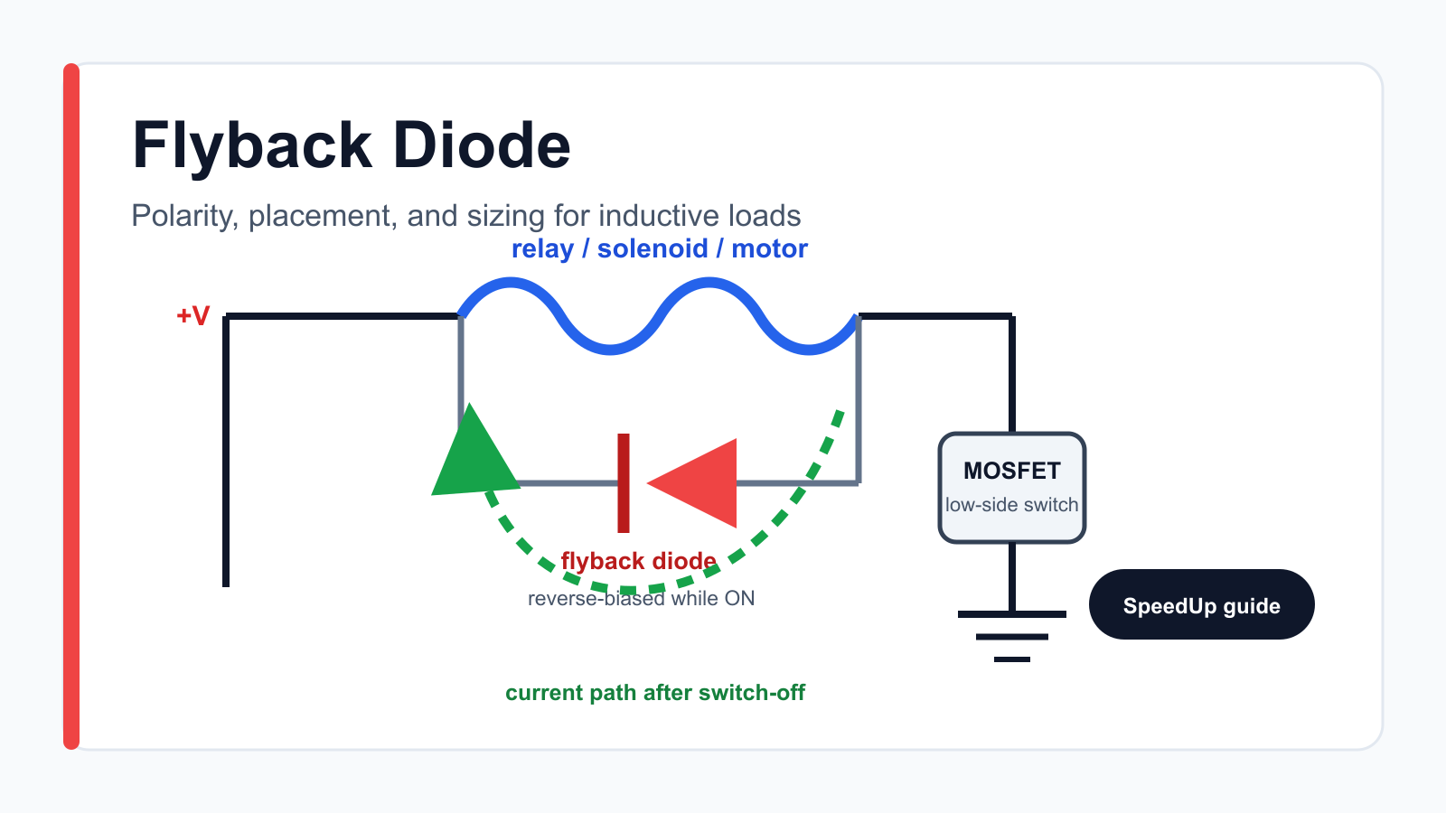
A flyback diode gives current from a DC inductive load—such as a relay coil, solenoid, or simple brushed-motor stage—a safe path when its switch turns off. For a low-side driver, connect the diode directly across the load with its cathode, usually the striped end, toward the positive supply and its anode toward the MOSFET or transistor. Choose it for the load current, reverse voltage, stored energy, switching rate, temperature, and required release time. Do not assume one diode across the load is correct for an AC coil, H-bridge, or three-phase BLDC inverter.
The diode is not there to carry normal load current. It is reverse-biased while the load is energized, then becomes forward-biased for a short time after switch-off. That simple detail protects the switch from an inductive voltage spike, but it also changes how quickly the relay, solenoid, or motor current decays.
Why Flyback Diodes Matter in Schematic Review
An inductor resists a sudden change in current. The magnetic energy stored immediately before turn-off is approximately E = ½LI². If the schematic opens the current path without providing a controlled alternative, the inductor raises the voltage until current finds a path through parasitic capacitance, MOSFET avalanche, insulation, an unintended IC protection structure, or an arc.
The visible symptom may be a failed transistor, MCU resets, corrupted sensor readings, EMI, contact wear, or a design that works on the bench but fails when the cable or load changes. A clean ERC result does not prove the clamp is present, correctly polarized, or fast enough for the mechanism. That is why inductive-load protection belongs in a complete schematic review checklist before PCB layout.
Nexperia’s power-switch guidance describes relays, solenoids, motors, and even long cables as inductive loads whose stored energy can damage a system when the load is disconnected. Its recommended options include a freewheeling diode across the load, a higher-voltage clamp, or a deliberately verified avalanche strategy—not simply leaving the switching device to absorb an unknown event.
Flyback Diode Schematic Checklist
| Review area | What to verify | Common failure |
|---|---|---|
| Load and topology | DC relay, solenoid, one-direction motor, H-bridge, BLDC inverter, AC coil, or remote cable | Using the simple diode topology where current must reverse |
| Polarity | Cathode to positive supply; anode to the switched side for a low-side DC driver | Forward-biasing the diode whenever the load turns on |
| Current rating | Initial flyback current, pulse duration, repetition rate, duty cycle, and temperature | Choosing from steady-state diode current alone |
| Reverse voltage | Supply tolerance, transients, diode VRRM, and the switch absolute maximum | Matching the rating to nominal supply voltage with no margin |
| Release behavior | Allowed relay release, solenoid drop-out, or motor coast time | Adding a low-voltage diode clamp and overlooking slow release |
| Placement | Short loop at the load or load connector; connector polarity and remote harness behavior | Putting the clamp far from the coil so cable inductance remains outside the loop |
| Built-in protection | Relay, driver IC, or smart switch datasheet and polarity requirements | Duplicating or fighting an internal clamp without understanding it |
Driving a relay, solenoid, or motor?
Describe the inductive load, supply, switch, current at turn-off, repetition rate, release-time target, and protection constraints. Create a free account to start a reviewable, editable KiCad first draft.
Flyback Diode Schematic: Correct Polarity

For the common low-side N-channel MOSFET circuit, the positive supply feeds one side of the coil and the MOSFET pulls the other side toward ground. The flyback diode goes across the coil. Its cathode connects to the supply side and its anode connects to the switched side.
While the MOSFET is on, the diode sees reverse voltage and should not conduct. At turn-off, coil current tries to keep flowing in the same direction. The switched node rises until the diode conducts, closing a local loop through the coil and diode. If the diode is reversed, it creates a near-short when the MOSFET turns on. If the diode is placed in series with the load, it does not provide the intended recirculation path.
Relays with a built-in suppression diode are polarity-sensitive even if the bare coil would not otherwise care about polarity. Check the exact orderable relay suffix and pinout before adding a second external diode or reversing the connector.
Where to Place the Diode
Place the clamp physically close to the inductive load, not merely close to the MOSFET. The goal is to make the turn-off current loop—load, diode, and short interconnect—as small as practical. Panasonic’s relay guidance recommends mounting the protective device in the immediate vicinity of the load and warns that excessive distance reduces effectiveness.
If a relay or solenoid sits off-board, put the diode at the coil or at the load-side connector when the wiring and service model allow it. A board-side clamp may still protect the switch, but the long harness remains part of the transient loop. Document connector polarity because reversing a load assembly that contains a diode can short the supply.
Placement also matters for PCB review. Keep the high-current recirculation loop out of sensitive analog ground, RF, reset, and sensor paths. Confirm copper width, diode thermal path, connector current, and return-path geometry in the KiCad schematic-to-layout checklist before routing begins.
How to Size a Flyback Diode
There is no universal “use a 1N4007” rule. A slow relay that switches a few times per minute, a PWM solenoid, and a brushed motor can place very different electrical and thermal stress on the diode.
1. Start with current at turn-off
The diode current immediately after switch-off is approximately the load current just before switch-off. Use the coil or motor operating current under worst-case supply, temperature, and load conditions—not the MCU pin current or an optimistic nominal value. Check the diode forward-current, surge-current, pulse-duration, and repetitive thermal limits.
2. Estimate stored energy and repetition
Stored inductive energy increases with the square of current: E = ½LI². A 100 mH coil carrying 200 mA stores about 2 mJ. That may be small for one event, but repetitive PWM or rapid cycling can turn pulse energy into a temperature problem. Use measured waveforms and component thermal data when switching is frequent.
3. Choose reverse-voltage margin from the real environment
While the load is on, the diode is reverse-biased by roughly the supply voltage. Supply tolerance, automotive or industrial transients, cable events, and wiring mistakes can raise the requirement. OMRON gives a simple relay-selection reference of reverse withstand voltage at least twice the supply voltage and forward current at least the load current for one of its surge-absorption examples; Panasonic publishes different guidance for some relay classes. Treat these as supplier-specific starting points and verify the diode, relay, switch, and system transient requirements together.
4. Check speed and recovery
A general-purpose rectifier can be adequate for a slowly operated DC relay, but high-frequency PWM and bridge commutation need diode recovery and switching-loss analysis. A Schottky diode has low forward voltage and little reverse-recovery charge, but its lower clamp voltage usually lets current decay more slowly, and its reverse-voltage and leakage characteristics may be limiting. “Faster diode” does not automatically mean “faster relay release.”
5. Verify the switch as part of the clamp
Check MOSFET or transistor voltage, current, safe operating area, avalanche rating, gate behavior, and driver-IC clamp structure. A MOSFET body diode is not automatically a substitute for a diode across a coil in a single low-side switch: the body diode is connected across the MOSFET, while the coil needs a complete current loop after the switch opens.
Diode, Zener, TVS, or Snubber?

A plain diode clamps at a low voltage, so it is gentle on the switch and efficient at suppressing the spike. The tradeoff is slow current decay. Both OMRON and Panasonic warn that coil-surge suppression can lengthen relay or solenoid release time. That matters when contact timing, mechanical drop-out, valve closing, safety interlocks, or high cycling speed are important.
A diode plus Zener, TVS clamp, or another higher-voltage suppression network allows a larger voltage across the coil after turn-off. The larger voltage drives current toward zero faster, but it increases voltage stress and pulse energy in the clamp. Nexperia’s power-switch application guidance compares freewheeling, TVS-clamp, active-clamp, and MOSFET-avalanche approaches. Use the load, driver, and switch datasheets to set the allowed clamp voltage rather than choosing a Zener value from supply voltage alone.
For AC coils, a single rectifier diode across the coil would conduct on one half-cycle. OMRON recommends diode suppression as a common DC-coil approach, while varistors or CR networks are typical for AC coils. RC snubbers and MOVs may also be used for contacts or AC loads, but their values, leakage, heating, safety ratings, and failure modes need application-specific design.
Application Boundaries: Relay, Solenoid, Brushed Motor, H-Bridge, and BLDC
| Application | Typical protection direction | Key review question |
|---|---|---|
| DC relay coil | Diode across coil; higher-voltage clamp if faster release is required | Does suppression change contact release timing or relay polarity? |
| DC solenoid or valve | Freewheel diode, diode-Zener, TVS, active clamp, or rated avalanche | How quickly must the actuator release, and how often does it switch? |
| One-direction brushed motor | Diode or clamp compatible with startup, stall, PWM, and coast behavior | Can the diode handle motor current, repetition, and required stopping time? |
| Bidirectional H-bridge | Bridge body diodes, external diodes, synchronous paths, TVS, and driver strategy | Where does current circulate in every switching state and direction? |
| Three-phase BLDC inverter | Per-switch recirculation, bus clamp, gate-drive timing, current sensing, and control | Have commutation, dead time, regeneration, and bus overvoltage been analyzed? |
| AC relay coil | Varistor or properly designed CR network, not one rectifier diode | Are component ratings and mains safety requirements satisfied? |
Example From a Real SpeedUp Project: When One Diode Is Not Enough

The three-phase motor inverter example exposes U, V, and W phase outputs, gate-control paths, current sensing, bus sensing, and fault feedback. A single flyback diode directly across this motor would conflict with bidirectional phase voltages and is not a substitute for the inverter’s MOSFET body-diode paths, external clamp choices, bus-energy handling, gate timing, and firmware.
The opposite case is also useful. SpeedUp’s desktop robot controller project explicitly notes that its current package does not contain motor drivers or actuator electronics. If a later revision adds a relay, solenoid, or brushed motor, the flyback path becomes a new schematic requirement; it should not be assumed to exist because the controller, regulator, and connectors already pass ERC.
Common Flyback Diode Mistakes
- Reversing the diode: it conducts during normal operation and can short the supply through the switch.
- Placing the diode in series: the inductive current still has no local loop when the switch opens.
- Assuming the MOSFET body diode is enough: its orientation may not provide the required path in a single low-side driver.
- Ignoring release time: a low-voltage clamp may keep a relay, contactor, valve, or solenoid energized longer than expected.
- Using nominal current only: motor stall, supply tolerance, temperature, PWM, and repetitive pulses can dominate stress.
- Putting the clamp far from the load: cable inductance and the enlarged loop can still generate noise and overshoot.
- Using one diode on an AC or bidirectional load: the normal operating voltage reverses, so the simple topology no longer applies.
- Copying a diode part number without checking its datasheet: package, leakage, VRRM, pulse current, temperature, and availability all matter.
What ERC and AI Schematic Review Can—and Cannot—Catch
ERC may flag an unconnected pin, conflicting pin types, or a missing power driver, but it normally does not know the relay’s stored energy, acceptable release time, motor stall current, harness inductance, or the MOSFET’s repetitive avalanche margin. It may also accept a diode that is electrically connected but reversed for the intended operating state.
An AI-generated schematic should therefore be treated as a first engineering draft. Ask the generator or reviewer to identify every inductive load, state the current path for switch-on and switch-off, name the suppression topology, expose component ratings, and flag unresolved release-time or safety requirements. Engineers still need to validate the schematic, layout, thermal behavior, firmware timing, sourcing, EMC, and compliance before production.
How SpeedUp Fits
SpeedUp can turn a product-level prompt into a structured schematic draft with named power, control, interface, and protection blocks. For a relay or solenoid controller, that draft should make the switch, load connector, supply, clamp, and review assumptions visible. The useful output is not an automatic promise that the diode is correct; it is an editable starting point where an engineer can verify polarity, ratings, release behavior, and PCB constraints before layout.
FAQ
What does a flyback diode do?
It provides a controlled path for inductive current after a switch turns off. This limits the voltage spike that would otherwise stress the transistor, MOSFET, driver IC, insulation, and nearby electronics.
Does every MOSFET driving a motor need a flyback diode?
Every inductive switching topology needs a valid current-recirculation and energy-management path, but that path is not always one diode across the motor. A one-direction low-side brushed-motor stage may use a diode across the motor. H-bridges and BLDC inverters use multiple switching and recirculation paths that must be analyzed for every state.
Can a Schottky diode be used as a flyback diode?
Yes, if its reverse-voltage, current, leakage, temperature, pulse-energy, and package ratings fit the circuit. Its low forward voltage reduces the clamp voltage and can slow current decay, so it is not automatically the best choice when fast relay or solenoid release matters.
Should the flyback diode be placed near the MOSFET or the coil?
Usually place it as close to the inductive load as practical so the recirculation loop is short. For a remote load, account for connector polarity and cable inductance; a board-side clamp may not eliminate the transient generated by the harness outside the local loop.
Why can a flyback diode make a relay release more slowly?
The diode clamps the coil to a low voltage after turn-off, so the current and magnetic field decay gradually. A higher-voltage diode-Zener or TVS solution can shorten release time, but the switch and clamp must be rated for the higher voltage and pulse energy.
Start Your Inductive-Load Circuit
Turn your driver and protection requirements into a reviewable schematic starting point.
Use SpeedUp to turn the product requirements into structured schematic sheets and an editable KiCad first draft for engineering review. Create a free account to begin.
Comments
No comments yet.
Leave a Reply