
Quick Answer
The MCP73831 is a common single-cell Li-Ion/Li-Polymer charger IC, but an MCP73831 charger circuit still needs careful schematic review before PCB layout. Check the input source, charge-current setting, battery connector, status output, thermal limits, load-sharing assumptions, protection parts, and whether the charger is isolated from noisy system loads. A working-looking schematic can still fail if the charge current is too high for the USB input, the battery connector is ambiguous, the thermal path is weak, or the system load interferes with charge termination.
For a KiCad project, treat the MCP73831 block as part of the whole power tree, not a standalone symbol. The charger touches USB or adapter input, battery safety, system power, mechanical placement, firmware-facing status, test points, and layout constraints. SpeedUp can help draft a reviewable KiCad schematic from requirements, but engineers should still verify the charger circuit against the Microchip datasheet and the actual battery pack.
Why MCP73831 Circuits Need More Than a Copy-Paste Schematic
Many engineers search for mcp73831 circuit or mcp73831 schematic because they want a quick charger block. The part looks simple: input, battery, programming resistor, status pin, and a few passive components. That simplicity is exactly why mistakes slip through.
The charger block is usually tied to decisions outside the IC:
- USB-C, Micro-USB, pin header, dock, or adapter input
- battery chemistry and capacity
- charge current and thermal dissipation
- product load while charging
- battery connector polarity and protection
- status LED or MCU charge-state input
- enclosure thermal behavior
- test points and bring-up procedure
- layout around the charger, battery node, and input capacitor
If those decisions are not visible in the schematic, the PCB layout may hide a system-level battery problem instead of solving it.
Designing a single-cell LiPo product?
Describe the battery, USB input, MCP73831 charge current, thermal limits, load sharing, status output, and safety constraints. Create a free account to start a reviewable, editable KiCad first draft.
MCP73831 Charger Circuit Checklist
Use this checklist before moving an MCP73831-based charger block into layout.
| Review area | What to check in the schematic | Why it matters before PCB layout |
|---|---|---|
| Part variant | Confirm the exact MCP73831/MCP73832 variant, charge voltage option, package, temperature range, and availability. | Small suffix differences can change voltage target, package, or sourcing assumptions. |
| Input source | Label whether the charger input comes from USB, USB-C, adapter, dock, or another regulated rail. | Input current limit, connector protection, cable behavior, and upstream voltage quality affect charging. |
| Charge current | Check the programming resistor value and compare charge current to battery capacity, USB budget, and thermal limits. | Over-aggressive charge current can overheat the IC or exceed the input source. |
| Battery connector | Name battery positive/negative clearly, include polarity/keying assumptions, and check connector footprint. | Battery connector mistakes are expensive and can be unsafe. |
| Battery protection | Decide whether protection is inside the cell pack or must be added on the board. | The charger IC is not the whole battery-safety system. |
| System load path | Decide whether the product can run while charging and whether load sharing or power-path control is needed. | A system load can affect charge termination, battery behavior, and user-visible reliability. |
| Status output | Route STAT to an LED, MCU input, or test point with the right pullup/current-limit assumptions. | Charge-state visibility helps bring-up, firmware, and user feedback. |
| Thermal behavior | Estimate worst-case dissipation and give the package enough copper and airflow for the product enclosure. | Linear chargers dissipate heat; schematic choices constrain layout. |
| Input/output capacitors | Use datasheet-recommended capacitors and voltage ratings close to the charger pins. | The layout must support stable charging and avoid noise on battery/input nodes. |
| Test access | Add test points for input voltage, battery node, status, ground, and system rail where useful. | Bring-up needs measurable nodes, especially on battery-powered products. |
| Layout constraints | Add notes for short battery/input paths, thermal copper, connector placement, and keepouts. | Layout quality is part of the charger design, not a separate afterthought. |
The goal is not to make the schematic large. The goal is to make the assumptions explicit enough that the layout engineer, firmware engineer, and reviewer can see the same power story.
Charge Current and Thermal Review
The charge-current setting deserves its own review pass. In an MCP73831 design, the charge current is not just a resistor choice; it is a product decision.
Before layout, answer these questions:
- What is the actual battery capacity?
- What charge rate is acceptable for this cell and product?
- Can the USB or adapter source provide the chosen current?
- What happens if the product is on while charging?
- How hot can the charger package get in the enclosure?
- Is there enough copper near the charger to spread heat?
- Does the product need a lower default charge current for safety margin?
Do not pick a high charge current just because a reference schematic uses one. Check the Microchip datasheet, the battery vendor's limits, the connector/input budget, and the thermal conditions of the real device.
Load Sharing and Power-Path Questions
Many MCP73831 mistakes come from the system-load question. A simple charger circuit may be fine when the product is off during charging. It may be less fine when the product is running from the same battery node while charging.
Review these cases:
| Product behavior | Schematic question | Risk if ignored |
|---|---|---|
| Charges only when off | Is the load disconnected or naturally inactive during charge? | User may expect operation while charging, but the circuit may not support it. |
| Runs while plugged in | Is there a defined power path or load-sharing arrangement? | System current can interfere with charge termination or thermal behavior. |
| MCU monitors charge state | Is STAT routed to a valid logic domain with safe pullup behavior? | Firmware may read unreliable or unsafe charge status. |
| User LED indicates charging | Is LED current appropriate and is the LED state documented? | The user may see confusing or dim status behavior. |
| Battery is removable | Is reverse insertion, connector keying, and exposed terminal behavior considered? | Mechanical and safety risk increases. |
If the device must run while charging, do not treat the charger as a complete power-management solution by itself. Add the missing power-path design explicitly or document why it is not needed.
Example From a Real SpeedUp Project
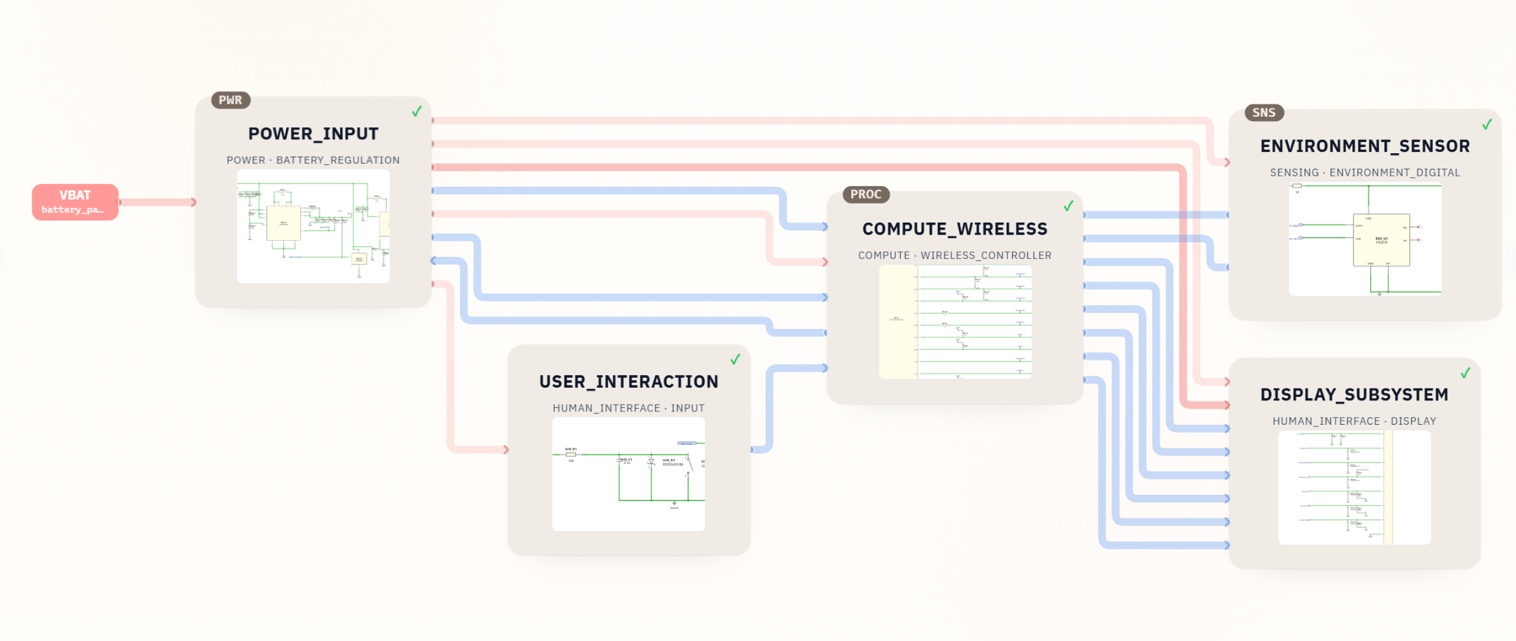
The Desktop Robot ESP32 KiCad schematic project is not an MCP73831 charger design. It is useful here because it shows how a generated KiCad project can separate power, compute, display, sensing, and user-interface sheets so the power path can be reviewed before layout.
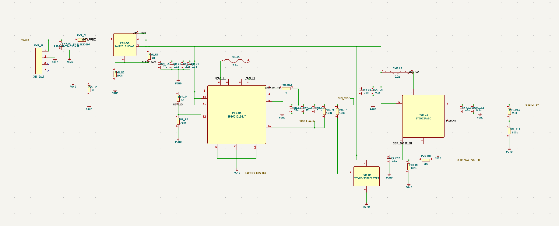
For an MCP73831-based design, the charger block should live in the same kind of reviewable power sheet. The reviewer should be able to see the input connector, charger IC, battery connector, charge-current programming, status output, system rail relationship, protection assumptions, and layout notes without hunting through a flat schematic.
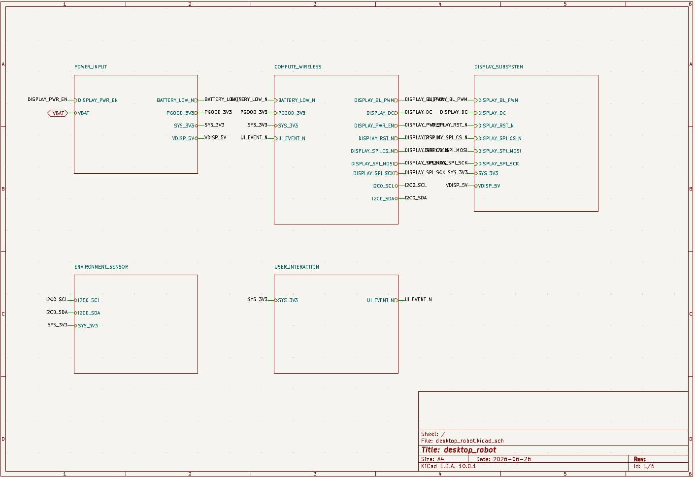
This is the kind of output SpeedUp is meant to accelerate: a structured first draft that can be opened, inspected, edited, and reviewed in KiCad.
What to Put in a SpeedUp Prompt for an MCP73831 Charger
If you want an AI-generated first draft for a battery-powered product, describe the charger as part of the system, not just as a part number.
Example prompt:
Design a compact single-cell Li-Ion powered sensor board as an editable KiCad project. Include an MCP73831 charger from USB-C 5 V input, a protected battery connector, a 3.3 V regulator for the MCU and sensors, charge-status indication, test points for input, battery, system rail, and status, and layout notes for thermal copper and battery/input routing. Make the design a first engineering draft for review, not a production-ready reference design.
That prompt gives the generated schematic a review target. The output should still be checked against the MCP73831 datasheet, the selected battery, connector footprint, enclosure, and manufacturing process.
Common Mistakes
- Copying an MCP73831 reference circuit without checking the exact part variant and charge-voltage option.
- Setting charge current without checking battery capacity, input-source budget, and thermal dissipation.
- Forgetting that a product load can interfere with charging if no load-sharing or power-path decision is made.
- Leaving STAT unused when the product needs user feedback, firmware awareness, or bring-up visibility.
- Assuming the battery pack includes protection without verifying the actual cell or connector assembly.
- Placing the charger far from the battery/input capacitors or without enough thermal copper.
- Treating the charger schematic as complete while the system rail, test points, and layout notes are still undefined.
How SpeedUp Fits
SpeedUp can help turn a product requirement into a structured KiCad schematic draft. For an MCP73831 charger design, that means SpeedUp can draft the charger block in context: input source, battery node, system rail, status signal, regulator, test points, and review notes.
The engineering work does not stop there. A human reviewer still needs to verify the datasheet details, charge current, battery safety, thermal limits, footprint assignments, layout constraints, and test procedure. The best use of SpeedUp is to shorten the path from product idea to reviewable KiCad project, then let the engineer spend more time on the decisions that actually determine whether the board is safe and buildable.
Related SpeedUp Projects and Guides
- Desktop Robot ESP32 KiCad Schematic Project Generated from a Prompt – a real generated KiCad project with a power sheet, system rails, and reviewable schematic structure.
- Battery Powered Sensor Circuit Design Checklist – a broader battery-powered design checklist that pairs naturally with charger review.
- What to Check Before Using an AI-Generated KiCad Schematic for PCB Layout – downstream layout-readiness checks after the charger and power tree are reviewed.
- KiCad Schematic Generator: From Product Prompt to Editable KiCad Project – the SpeedUp workflow for turning product requirements into a KiCad schematic draft.
- How to Review AI-Generated KiCad Schematics Before PCB Layout – a general schematic review process before layout.
FAQ
What is MCP73831?
MCP73831 is a Microchip single-cell Li-Ion/Li-Polymer charge-management IC family. Use the official Microchip MCP73831 product page and MCP73831/MCP73832 datasheet for exact voltage options, package details, pin behavior, and application limits.
Is MCP73831 enough for a complete battery power system?
No. It can be the charger IC, but the whole system may also need input protection, battery protection, load sharing or power-path control, regulation, status indication, test points, thermal review, and layout constraints.
What should I check first in an MCP73831 schematic?
Start with the exact part variant, input source, charge-current setting, battery connector, STAT routing, and whether the product load is active while charging. Then review capacitors, protection, thermal behavior, footprints, and layout notes.
Can I use MCP73831 with USB-C?
Yes, but the USB-C input must be designed correctly. The schematic still needs the right connector assumptions, CC resistors or upstream USB-C handling as appropriate, input protection, current budget, and a clear connection from 5 V input to the charger.
Can AI generate an MCP73831 charger circuit?
AI can draft a first schematic block and place it in a larger KiCad project, but the result still needs engineering review against the datasheet, battery requirements, thermal limits, PCB layout, and test procedure.
Start Your LiPo Charger Project
Turn your battery and charging requirements into a reviewable KiCad first draft.
Use SpeedUp to turn the product requirements into structured schematic sheets and an editable KiCad first draft for engineering review. Create a free account to begin.
Comments
No comments yet.
Leave a Reply