
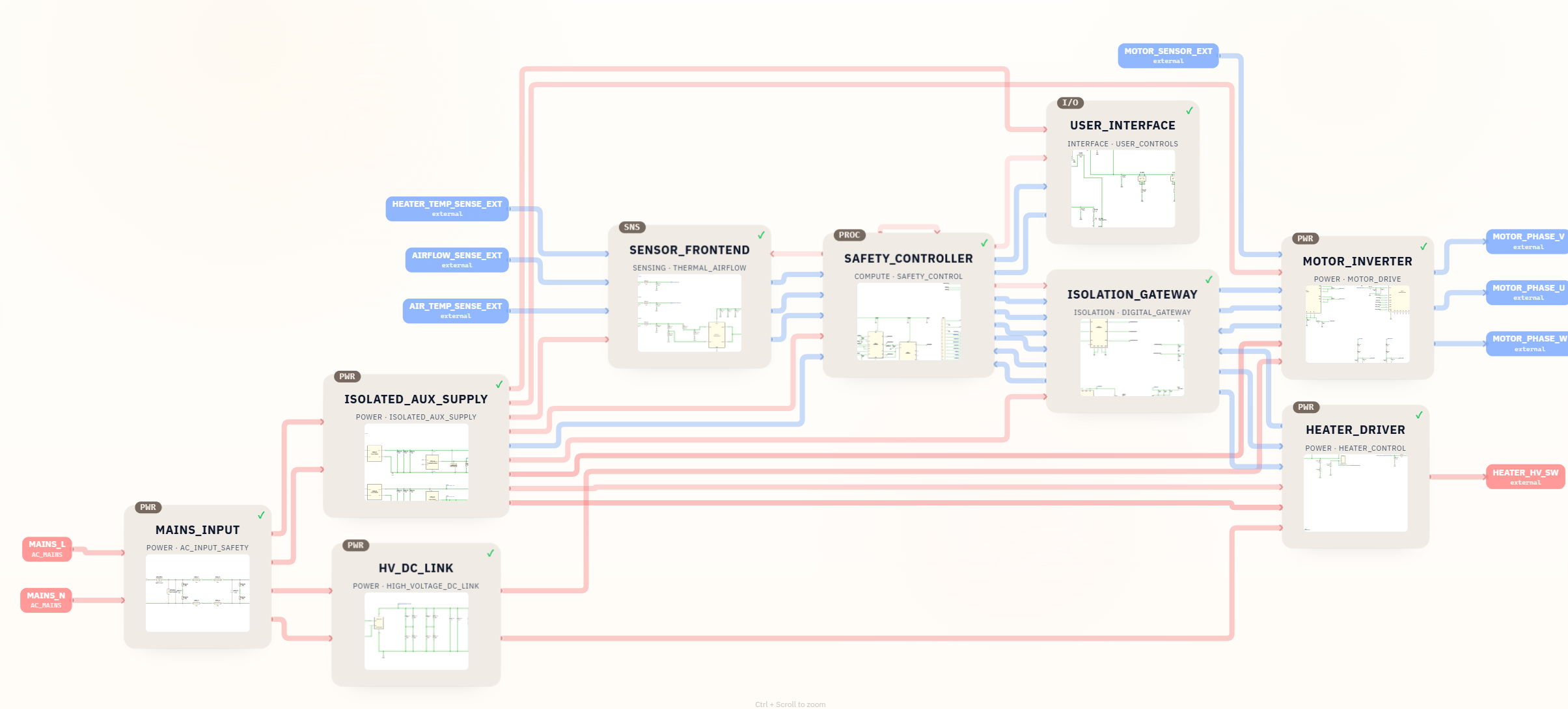
This project shows how SpeedUp turned a short product idea into an editable KiCad hair dryer schematic. The original prompt was only: "design a portable high speed hair dryer." From that input, SpeedUp generated nine hierarchical sheets covering AC mains input, an isolated auxiliary supply, a high-voltage DC link, a safety controller, temperature and airflow sensing, an isolation gateway, a three-phase motor inverter, a heater driver, and a user interface block.
This is a first engineering draft for review, not a production-ready hair dryer reference design. The source package contains hair_dryer.kicad_pro, the top-level hair_dryer.kicad_sch, nine module sheets, CSV/XLSX BOM exports, and local symbol and footprint libraries. It does not include a PCB layout.
If you are comparing this project to the broader prompt-to-circuit workflow, read the related guide to the AI schematic generator for KiCad circuit projects.
Project Summary
| Field | Details |
|---|---|
| Project | Portable high-speed hair dryer circuit design |
| Input | Natural-language prompt |
| Output | Editable KiCad 10 schematic project, BOM, and local symbol/footprint libraries |
| Key modules | MAINS_INPUT, ISOLATED_AUX_SUPPLY, HV_DC_LINK, SENSOR_FRONTEND, SAFETY_CONTROLLER, ISOLATION_GATEWAY, MOTOR_INVERTER, HEATER_DRIVER, USER_INTERFACE |
| Included files | hair_dryer.kicad_pro, top-level and nine hierarchical schematic sheets, CSV/XLSX BOM, 25 symbol libraries, 59 footprint files, and project-evidence images |
| Next engineering work | BOM and footprint review, PCB layout, firmware, mechanical design, thermal and motor validation, regulatory review, and safety-test evidence |
| Status | First engineering draft for review |
The Prompt
The project starts with a compact product request:
design a portable high speed hair dryer
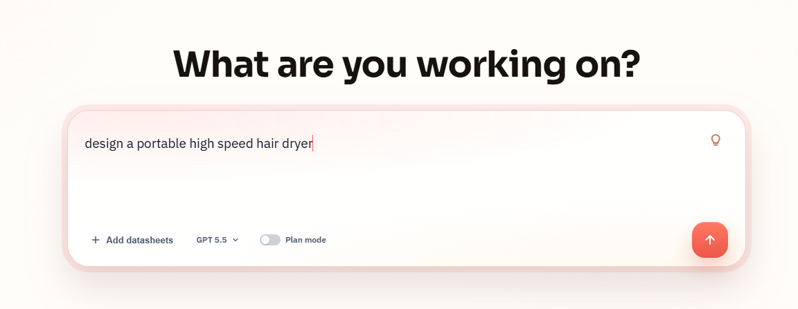
In the generated result, "portable" is interpreted as a handheld appliance form factor rather than a battery-powered dryer. The architecture shown here is built around AC mains input and a high-voltage DC link, so any production version would need appliance-level safety review.
What SpeedUp Generated
SpeedUp turned the prompt into a structured hair dryer schematic concept with:
- A block diagram for the complete electrical architecture.
- An editable KiCad project with
hair_dryer.kicad_pro, a top-levelhair_dryer.kicad_sch, and nine hierarchical module sheets. - A
MAINS_INPUTblock for AC line and neutral entry. - An
ISOLATED_AUX_SUPPLYblock for low-voltage auxiliary rails. - An
HV_DC_LINKblock for the high-voltage bus feeding power stages. - A
SENSOR_FRONTENDblock for heater temperature, air temperature, and airflow sensing. - A
SAFETY_CONTROLLERblock that collects sensor signals and commands heater and motor control paths. - An
ISOLATION_GATEWAYblock between the controller and primary-side power electronics. - A
MOTOR_INVERTERblock with U, V, and W motor phase outputs. - A
HEATER_DRIVERblock for controlled high-voltage heater switching. - A downloadable source package with the KiCad project, 124-line-item BOM, 25 local symbol libraries, 59 local footprint files, and prompt, block-diagram, and top-level-schematic images.
Want to create a motor-control appliance like this?
Describe your own motor-control appliance requirements and create a free account to start a reviewable engineering draft.
Why a Schematic Walkthrough Matters
Many public hair dryer resources explain basic repair, outlet load, or simple wiring diagrams. Those are useful, but they usually do not show how a modern high-speed dryer concept can be broken into reviewable engineering modules.
This project is different because it walks through a generated schematic-level architecture: power input, high-voltage bus, sensing, safety control, isolation, motor drive, and heater drive. It is not a finished production design, but it gives engineers a concrete starting point for asking the right review questions.
Project Architecture
The generated architecture splits the hair dryer into power, sensing, control, isolation, motor, heater, and user-interface domains.
MAINS_INPUT: acceptsMAINS_LandMAINS_Nand routes the AC input toward filtering and downstream power conversion.ISOLATED_AUX_SUPPLY: creates auxiliary rails for control and sensing from the mains-side power path.HV_DC_LINK: creates the high-voltage DC bus used by the motor and heater power stages.SENSOR_FRONTEND: conditions external heater temperature, air temperature, and airflow signals.SAFETY_CONTROLLER: reads sensor signals, monitors fault states, and issues motor and heater commands.ISOLATION_GATEWAY: bridges low-voltage control signals into isolated primary-side control paths.MOTOR_INVERTER: drives the high-speed motor withMOTOR_PHASE_U,MOTOR_PHASE_V, andMOTOR_PHASE_Woutputs.HEATER_DRIVER: switches the high-voltage heater path throughHEATER_HV_SW.USER_INTERFACE: connects the human control/status side of the product to the controller.
The overall shape is closer to a modern high-speed or brushless-style dryer than to a very simple universal-motor hair dryer. The architecture includes a motor inverter and multiple safety feedback paths, which are important for high-speed motor control and heater supervision.
Top-Level KiCad Schematic Output
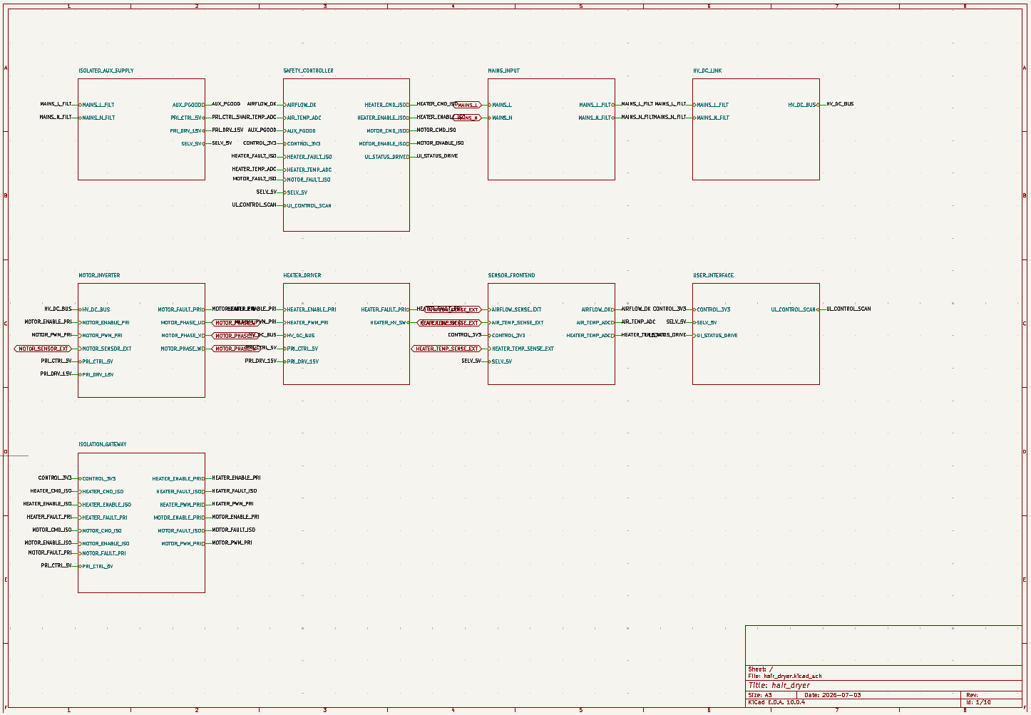
The top-level schematic uses a clear sheet hierarchy rather than placing every detail on one page. That makes the first review pass easier: engineers can inspect whether the safety controller sees the right temperature and airflow inputs, whether isolation boundaries are explicit, and whether the motor and heater paths are separated from low-voltage control logic.
The schematic images expose the hierarchy, named interfaces, and circuit intent needed for a structured engineering review. They should be used to resolve power, isolation, motor-control, sensing, heater, and safety decisions before downstream implementation.
Power Input and High-Voltage DC Link
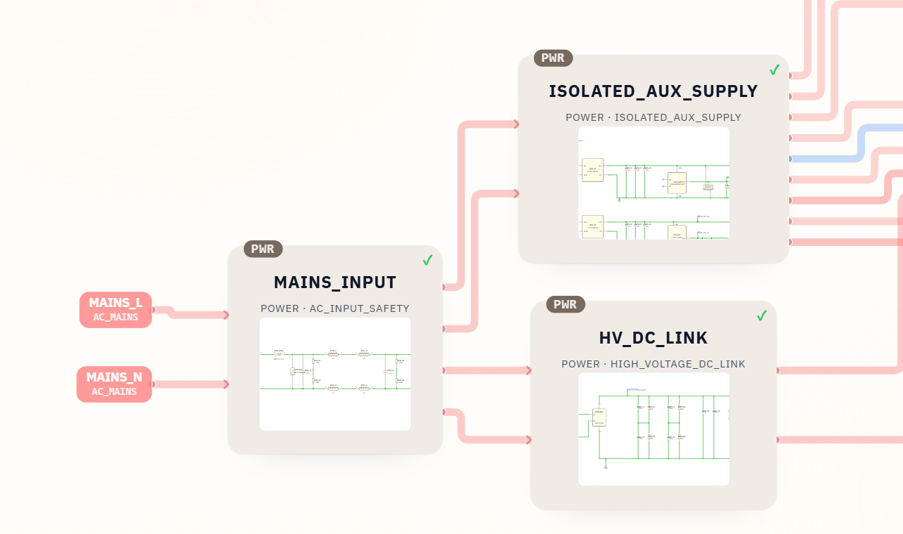
A hair dryer is a high-power appliance, so the power entry and high-voltage bus deserve the most conservative review. The generated design starts with AC mains line and neutral, routes that into a mains input block, then separates auxiliary low-voltage power from the high-voltage DC link that feeds the motor and heater paths.
This is the correct architectural direction for a high-speed dryer concept, but it is also the highest-risk part of the design. A production version would need qualified review for fuse strategy, surge protection, creepage and clearance, inrush current, EMI filtering, earth or double-insulation strategy, rectification, bulk capacitance, leakage current, thermal rise, and fault containment.
Do not treat this schematic screenshot as a safe mains design. It is a first draft that identifies the modules that must exist, not a validated appliance power supply.
Sensor Frontend for Temperature and Airflow
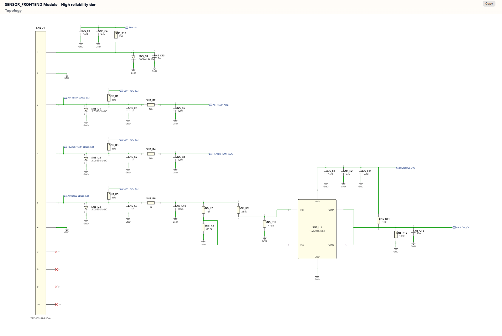
The SENSOR_FRONTEND block gives the safety controller the information it needs to decide whether the heater and motor can operate safely. The screenshot shows inputs for:
AIR_TEMP_SENSE_EXTHEATER_TEMP_SENSE_EXTAIRFLOW_SENSE_EXTSENSOR_5V_EXT
It also shows conditioned signals such as AIR_TEMP_ADC, HEATER_TEMP_ADC, and AIRFLOW_OK. This matters because a hair dryer should not treat the heater as an isolated load. Heat output must be coordinated with airflow, air temperature, heater temperature, motor state, and fault handling.
Before production, the sensor frontend needs review for sensor selection, ADC scaling, filtering, ESD protection, thermal placement, airflow sensor response time, open/short detection, fault thresholds, and what happens when a sensor cable is disconnected.
Safety Controller
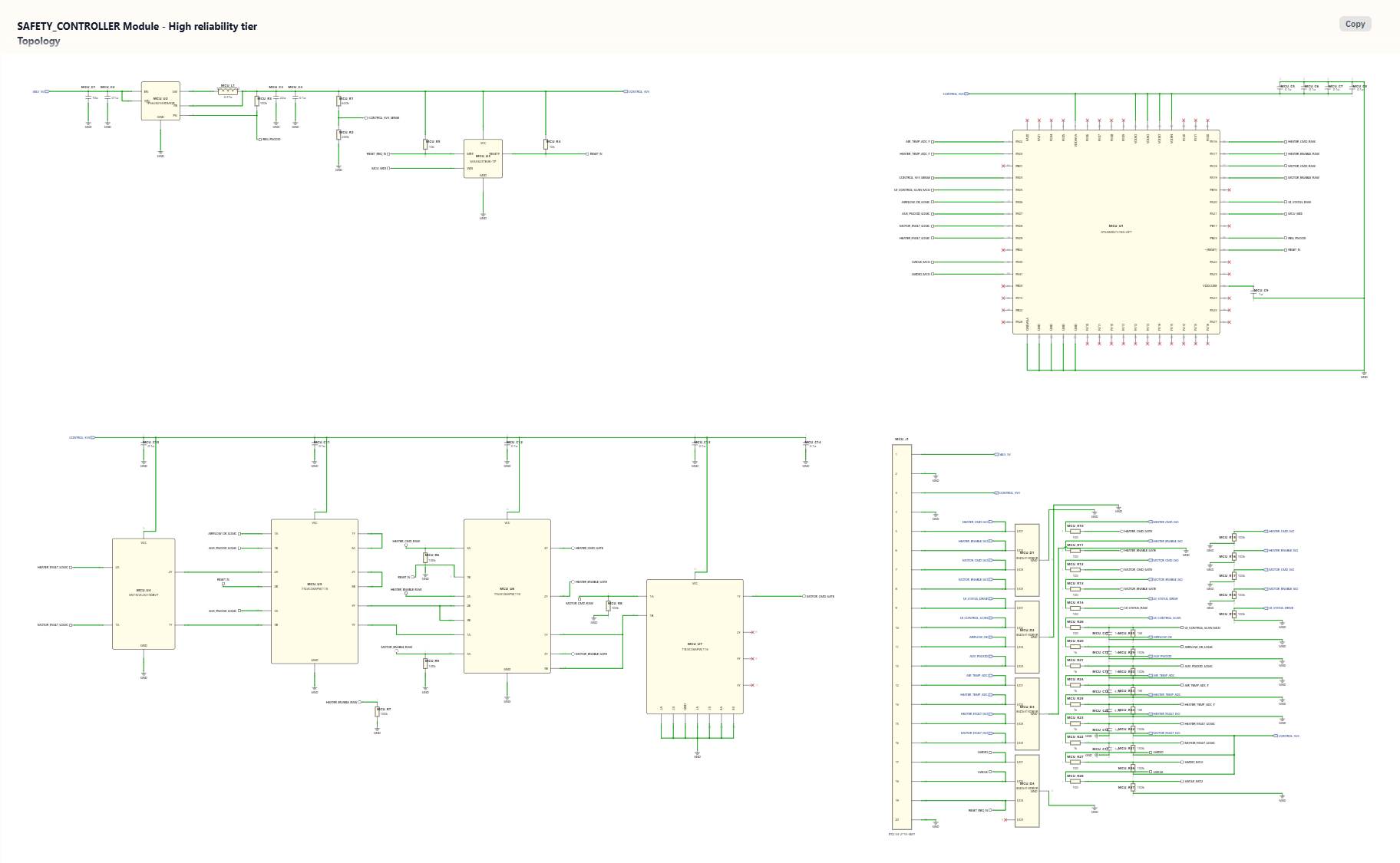
The SAFETY_CONTROLLER is the logic center of the generated design. It receives temperature and airflow feedback, watches motor and heater fault lines, and sends commands such as motor enable, heater enable, heater command, and motor command toward the isolated drive path.
This block is important because the product is not just a motor and a heating element. A high-speed hair dryer needs coordinated control: the heater should not run without airflow, the motor should not continue after a dangerous thermal event, and the user interface should not bypass safety thresholds.
Review this part for MCU pin assignments, watchdog behavior, brownout handling, reset logic, ADC protection, isolation signal defaults, fault latching, startup sequence, shutdown sequence, and firmware behavior under every sensor and power fault.
Motor Inverter for the High-Speed Fan
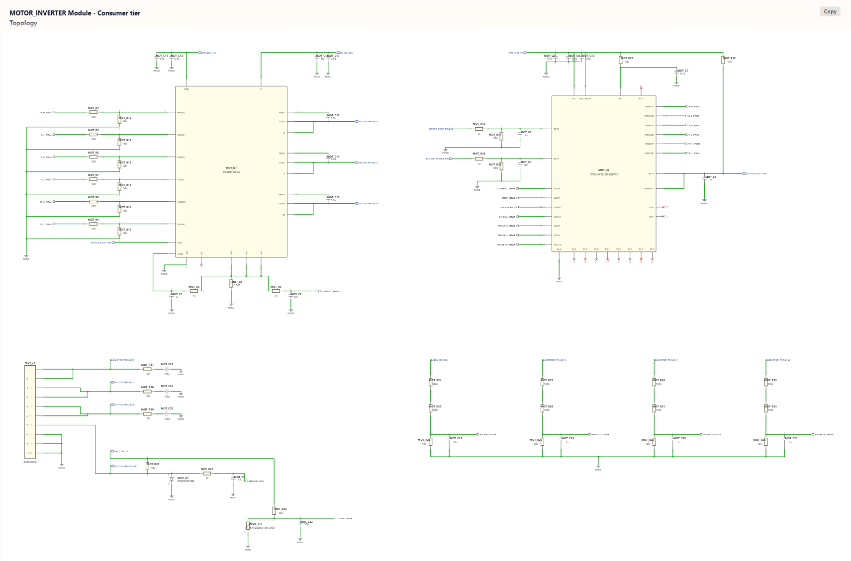
The generated MOTOR_INVERTER block includes U, V, and W motor phase outputs, which makes it a better match for a brushless or BLDC-style high-speed hair dryer concept than for a basic brushed-motor appliance. The detail screenshot also shows control inputs, fault feedback, current sensing, high-voltage bus sensing, phase sensing, and temperature sensing paths.
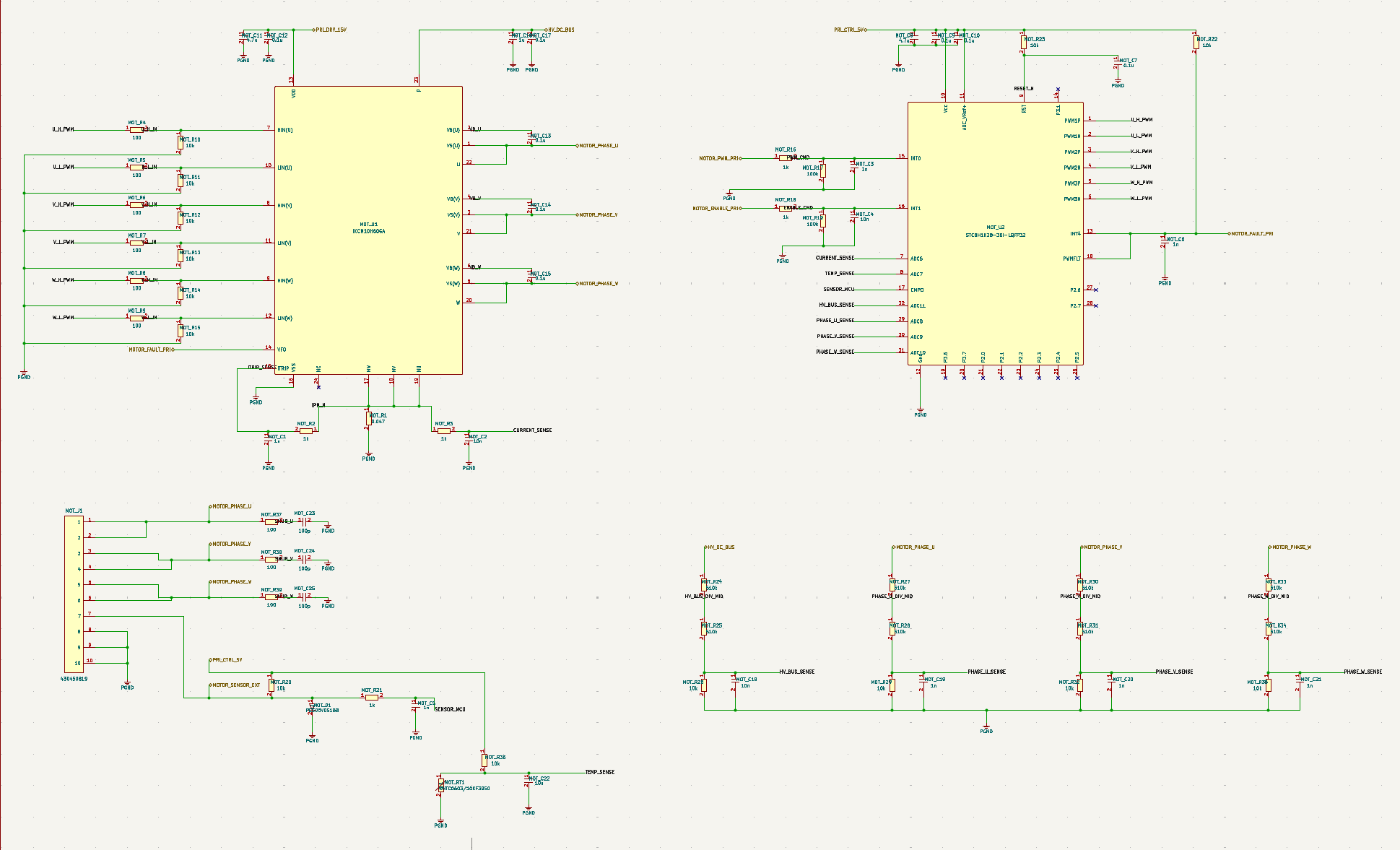
A single diode placed across a load is appropriate for some DC relay, solenoid, and brushed-motor stages, but it is not a substitute for the recirculation paths, switching-device behavior, and protection strategy required by this three-phase inverter. See the flyback diode guide for the simpler topology and its limits.
For an actual product, this block needs careful motor-specific validation. The correct inverter design depends on the motor winding, voltage, speed, commutation method, control firmware, acoustic target, thermal envelope, stall behavior, and enclosure airflow. It also needs layout review for switching loops, gate drive, current sensing, DC bus decoupling, EMI, and isolation from user-accessible surfaces.
Heater Driver
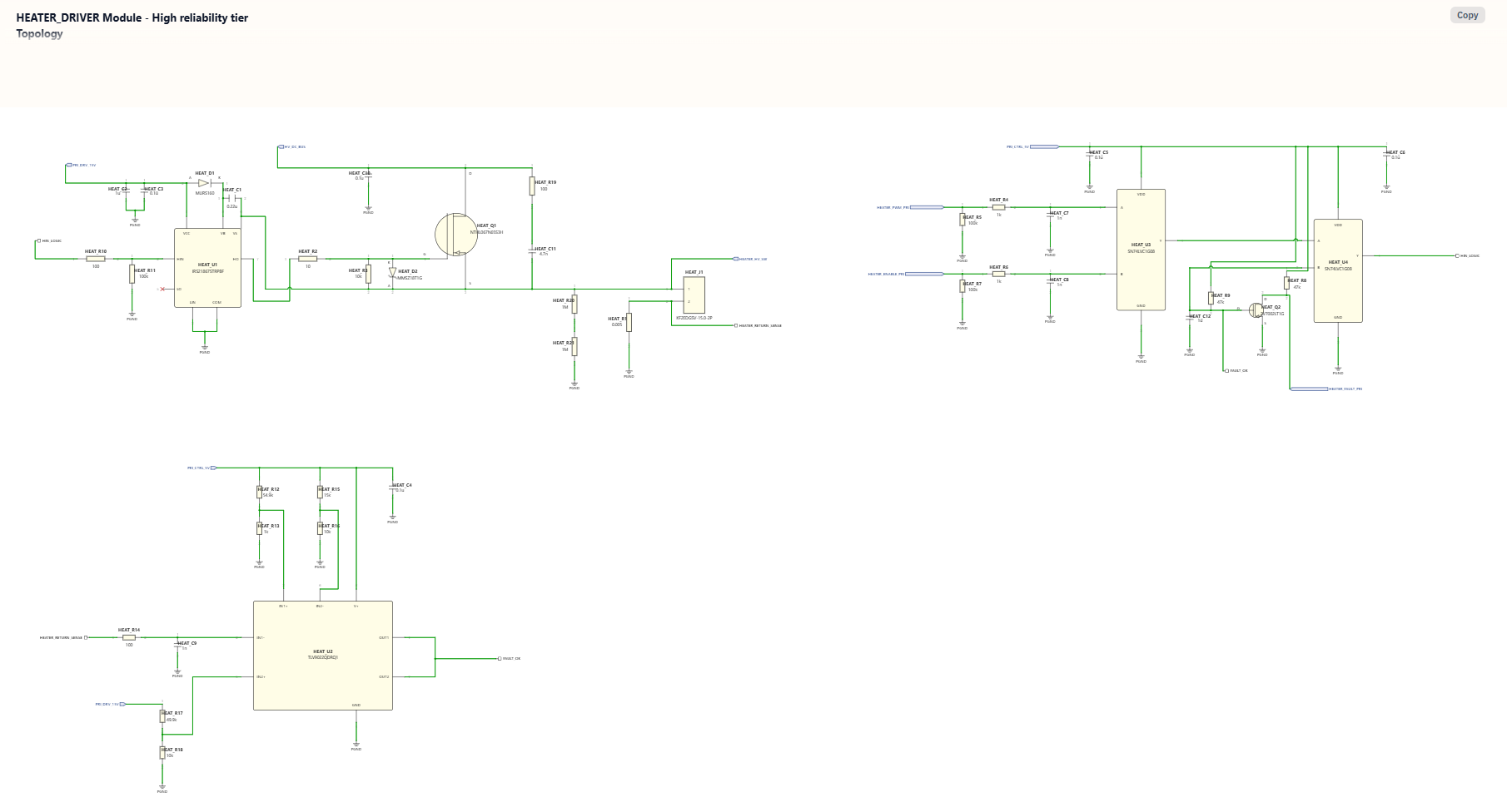
The HEATER_DRIVER block is responsible for controlled heater switching, not just connecting a resistive element across mains. The screenshot shows a high-voltage heater switch path, control input, enable input, PWM-related control, and fault/sense feedback.
This is where a generated schematic must be reviewed very carefully. Hair dryer heater control affects user safety, enclosure temperature, outlet load, product lifetime, and regulatory compliance. A production design needs independent thermal protection, flame-retardant material choices, heater wire and insulation validation, fan-heater interlocks, airflow obstruction behavior, and tests for single-fault conditions.
What the Generated Schematic Gets Right at the Architecture Level
At the architecture level, the generated design has several useful review qualities:
- It separates high-voltage power, low-voltage control, sensing, motor drive, and heater drive.
- It gives the safety controller explicit temperature and airflow inputs.
- It routes heater and motor command signals through an isolation gateway.
- It exposes motor phase outputs and feedback signals instead of hiding the motor as a black box.
- It includes both heater fault and motor fault feedback paths.
- It keeps user-interface control separate from power-stage switching.
Those are the right categories to review first when turning a vague product idea into an engineering artifact.
What Still Needs Human Review
This project is intended as a first engineering draft. Before a hair dryer design can be treated as board-ready or product-ready, review:
- Mains safety, fuse strategy, surge protection, creepage, clearance, insulation class, and enclosure safety.
- AC input filtering, rectification, inrush current, HV DC bus capacitance, discharge paths, and EMI behavior.
- Motor type, speed target, winding data, voltage range, current limits, commutation method, acoustic behavior, and thermal model.
- Motor inverter gate drive, switching losses, current sense, phase sense, DC bus sense, layout loops, isolation, and firmware protection.
- Heater element power, switching method, thermal cutoff strategy, airflow interlock, obstruction behavior, and single-fault safety.
- Temperature sensor placement, airflow sensor placement, response time, open/short detection, and ADC scaling.
- Isolation barrier requirements between user controls, low-voltage logic, and primary-side power electronics.
- Firmware startup/shutdown sequence, fault latching, watchdog, brownout handling, and recovery behavior.
- PCB layout, component packages, footprints, mechanical fit, airflow path, vibration, and manufacturability.
- Regulatory requirements for appliance safety, EMC, materials, labeling, and production test.
BOM and Engineering Handoff
The included BOM contains 124 line items and 343 placed quantities. It gives engineers a concrete component and sourcing review surface across the mains, isolated supply, high-voltage DC link, motor inverter, heater, safety controller, sensing, isolation, and user-interface sheets.
Before using this design for layout or procurement, create or request:
- A controlled schematic revision and design-review record.
- BOM review with validated MPNs, quantities, packages, ratings, land patterns, alternates, and sourcing notes.
- PCB layout, stack-up, Gerbers, drill files, pick-and-place, and assembly drawings.
- Firmware for motor control, heater control, safety logic, UI, and fault handling.
- Motor, heater, sensor, and enclosure specifications.
- Thermal, airflow, EMI, safety, and regulatory test plans.
Related SpeedUp Projects and Guides
- AI schematic generator for KiCad circuit projects explains the broader prompt-to-circuit workflow behind this project.
- Smart ring circuit design with nRF52832 and MAX30102 shows a lower-voltage wearable example with sensing, BLE, and power-management review notes.
- nRF54L15 development board KiCad project is a better comparison point for a board-oriented project workflow.
FAQ
What are the main electrical components of a hair dryer circuit?
A complete hair dryer circuit usually includes an AC input stage, protection and filtering, a heater power path, a fan motor drive, temperature sensing, airflow sensing, user controls, and safety shutoff logic. In this generated high-speed design, SpeedUp also separates the architecture into an HV DC link, isolated auxiliary supply, safety controller, isolation gateway, motor inverter, and heater driver.
Is this a brushless hair dryer schematic?
The generated design includes a three-phase motor inverter with MOTOR_PHASE_U, MOTOR_PHASE_V, and MOTOR_PHASE_W, which matches the architecture of a brushless or BLDC-style high-speed hair dryer concept. However, the supplied package does not include the motor datasheet, firmware, or validation data needed to call it a finished brushless dryer reference design.
How does the motor in this hair dryer design work?
At the schematic level, the motor inverter takes control signals from the safety/control side and drives three motor phases from the high-voltage bus. A production design would need motor-specific control firmware, current sensing, phase sensing, speed feedback or sensorless estimation, stall protection, and EMI-aware layout.
Is the heating part of a hair dryer just a resistor?
The heating element is often resistive, but a safe product needs much more than a resistor. It needs controlled switching, airflow coordination, thermal sensing, cutoff behavior, insulation, fault handling, and enclosure-level validation. This generated design includes a separate heater driver and heater fault feedback path to make those review points visible.
Does a hair dryer need its own circuit?
That question usually refers to the wall outlet or household branch circuit, not the internal schematic. Many hair dryers draw high current and should be used only on a properly rated outlet. For product design, the internal circuit must still handle high power safely through input protection, current limits, thermal protection, and compliance testing.
Is this hair dryer circuit production ready?
No. This is a first engineering draft generated for review and iteration. It needs BOM review, PCB layout, firmware, thermal testing, motor validation, heater-safety validation, EMC work, and appliance-safety certification before production.
What files are included in the downloadable package?
The ZIP includes hair_dryer.kicad_pro, the top-level hair_dryer.kicad_sch, nine hierarchical schematic sheets, a 124-line-item / 343-placed-quantity BOM in CSV and XLSX formats, 25 symbol libraries, 59 footprint files, and project-evidence images. No .kicad_pcb is included.
Can I generate a similar circuit from my own prompt?
Yes. SpeedUp is designed to turn a natural-language hardware idea into structured engineering artifacts such as architecture diagrams, schematic screenshots, subsystem details, and review packages that engineers can inspect and refine.
Download the Hair Dryer KiCad Source
Use this hair dryer ZIP as a review starting point for the generated editable KiCad schematic. It includes the project and schematic source, nine module sheets, BOM exports, local symbol and footprint libraries, and project-evidence images; add a reviewed PCB layout, firmware, mechanical CAD, reinforced-insulation and creepage validation, thermal and motor testing, appliance-safety certification, Gerbers, production tests, and manufacturing-release documentation before treating it as a complete engineering handoff.
Create Your Own Motor-Control Appliance
Turn your own motor-control appliance brief into reviewable engineering artifacts.
Use SpeedUp to generate structured schematic sheets and an editable KiCad project for engineering review. Create a free account to begin.
Comments
No comments yet.
Leave a Reply