
Quick Answer
The SN65HVD230 is a 3.3 V CAN transceiver, so a good SN65HVD230 schematic is not just the IC symbol wired to CANH and CANL. Before PCB layout, review the 3.3 V supply, TXD/RXD logic connections, CANH/CANL bus pins, termination strategy, R/S slope-control or standby behavior, connector pinout, ESD protection, common-mode and fault assumptions, test points, and whether the selected part is still the best fit for a new design.
For a KiCad project, treat the CAN transceiver as an interface block between a microcontroller CAN controller and the outside bus. The schematic should show what the transceiver connects to, how the bus leaves the board, whether the node terminates the bus, how standby is controlled, and what the layout engineer must preserve. SpeedUp can help draft a reviewable KiCad schematic from a product prompt, but engineers should still verify the CAN block against the TI datasheet, the network topology, and the target product environment.
Why SN65HVD230 Schematics Need System-Level Review
Searches for sn65hvd230 schematic often return datasheets, breakout boards, module schematics, forum reviews, and reference designs. Those are useful, but they do not answer the most important product question: what kind of CAN node are you building?
A CAN transceiver circuit changes depending on:
- whether the board is an end node or a middle node
- whether the network already has 120 ohm termination at both ends
- whether the connector is an automotive, industrial, internal harness, or lab connector
- whether the MCU has a built-in CAN controller or uses a separate controller
- whether the design needs low-power standby
- what ESD, surge, and fault conditions the bus may see
- whether the product is a prototype, field device, motor controller, sensor node, or diagnostic tool
- whether a newer CAN or CAN FD transceiver is a better choice for the application
That is why the schematic should not be a floating module copied from a breakout board. It should explain the node, the bus, the control pins, and the layout constraints.
Building a 3.3 V CAN node?
Describe the controller, SN65HVD230 interface, connector, termination, protection, standby behavior, and network role. Create a free account to start a reviewable, editable KiCad first draft.
SN65HVD230 CAN Bus Schematic Checklist
Use this checklist before moving an SN65HVD230-based CAN block into PCB layout.
| Review area | What to check in the schematic | Why it matters before PCB layout |
|---|---|---|
| Part choice | Confirm SN65HVD230, package, availability, and whether a newer TI alternative is more appropriate. | TI lists newer related transceivers; a new design should not choose an older part blindly. |
| Supply rail | Verify the 3.3 V supply, local decoupling, current budget, and power-domain naming. | The transceiver depends on a stable local rail and clean return path. |
| MCU interface | Check TXD, RXD, logic levels, pin names, and whether the MCU actually has a CAN controller. | A CAN transceiver is not a CAN controller; it converts controller signals to the bus physical layer. |
| R/S pin behavior | Decide whether R/S is tied for high-speed mode, uses slope control, or is driven for standby/listen behavior. | This pin affects emissions, power mode, and whether the device can transmit. |
| CANH/CANL pins | Route CANH and CANL as a pair with clear names and connector mapping. | Layout must preserve the bus pair and avoid accidental swaps. |
| Termination | Decide whether this board needs 120 ohm termination, split termination, optional jumper termination, or no termination. | Wrong termination can break bus reliability, especially when multiple nodes are connected. |
| ESD and protection | Add or document TVS/ESD strategy, common-mode choke if used, and expected bus fault environment. | External CAN connectors can face real-world stress that the IC alone may not cover. |
| Connector and cable | Label connector pins, shield/chassis assumptions, ground reference, and harness orientation. | CAN issues often start at the connector and cable, not the IC. |
| Test access | Add test points for 3.3 V, ground, TXD, RXD, CANH, CANL, and optional standby/slope node. | Bring-up and bus debugging need measurable nodes. |
| Layout notes | Add notes for short decoupling paths, bus pair routing, connector placement, protection placement, and ground strategy. | A clean schematic still needs physical constraints for a reliable bus. |
The schematic should answer the reviewer's first questions without forcing them to infer the product architecture from a tiny IC block.
Termination and Connector Review
CAN bus termination is a system decision. A single schematic block cannot decide it unless the product's position on the bus is known.
For the complete endpoint topology, two-resistor placement rule, 60-ohm powered-off resistance test, and split-termination tradeoffs, use the CAN bus termination resistor placement and testing guide.
Before layout, write down:
- Is this board always one end of the bus?
- Is this board sometimes plugged into an already terminated network?
- Should termination be fixed, jumper-selectable, switchable, or omitted?
- Does the connector include CANH, CANL, ground, shield, power, or wake signals?
- Does the product need a common-mode choke, ESD array, or TVS diode near the connector?
- Are CANH and CANL clearly named from IC pins to connector pins?
- Are test pads available for oscilloscope probing during bring-up?
If the product may be used in multiple bus positions, a selectable termination option can be more useful than hard-wiring 120 ohms. If the product is a fixed endpoint, permanent termination may be simpler. Either way, the schematic should say why.
R/S Pin, Slope Control, and Standby
The R/S pin is one of the review points that gets lost in quick SN65HVD230 circuits. TI documents that the SN65HVD230/SN65HVD231 R/S pin can select high-speed operation, slope-controlled operation, or a low-power mode depending on how the pin is connected or driven.
In a schematic review, ask:
- Is R/S tied low for high-speed operation?
- Is a resistor used for slope control to reduce emissions?
- Is R/S controlled by the MCU for standby or listen-only behavior?
- Does firmware know which mode the hardware selects?
- Is the default state safe during reset and power-up?
- Does the design need wake behavior, or only normal operation?
For a field product, this should not be left as an unexplained net. Name the control signal and document the intended operating mode.
Example From a Real SpeedUp Project
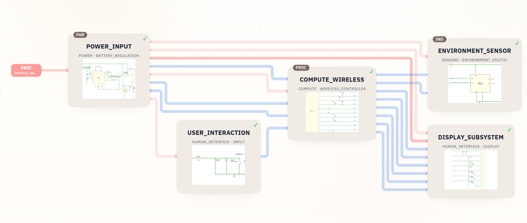
The Desktop Robot ESP32 KiCad schematic project is not an SN65HVD230 CAN node. It is useful here because it shows the review workflow SpeedUp aims to create: a product prompt becomes a structured KiCad project with named sheets, visible interfaces, and blocks that can be inspected before layout.
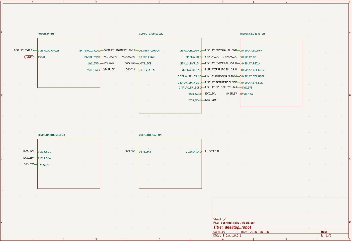
For a CAN sensor node, you would want the same structure: power input, MCU or CAN controller, SN65HVD230 transceiver, connector, protection, termination, test points, and layout notes. The generated project should make those blocks reviewable in KiCad before a board is routed.
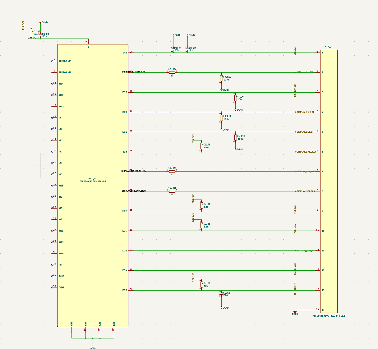
The evidence is not that the desktop robot contains a CAN transceiver. The evidence is the workflow: structured schematic generation gives engineers a place to inspect the decisions that matter before layout.
What to Put in a SpeedUp Prompt for an SN65HVD230 CAN Node
If you want an AI-generated first draft for a CAN interface, describe the whole node, not just the transceiver part number.
Example prompt:
Design a 3.3 V CAN sensor node as an editable KiCad project. Include an MCU with CAN controller support, an SN65HVD230 CAN transceiver, CANH/CANL connector, optional selectable 120 ohm termination, ESD protection near the connector, R/S slope-control or standby wiring, 3.3 V power regulation, test points for TXD, RXD, CANH, CANL, 3.3 V, and ground, and layout notes for bus routing and protection placement. Make the design a first engineering draft for review, not a production-ready reference design.
That prompt gives the generated schematic enough context to be useful. The engineer still needs to verify the part choice, network topology, ESD strategy, termination, firmware behavior, connector pinout, layout, and compliance needs.
Common Mistakes
- Treating the SN65HVD230 as a CAN controller. It is a transceiver; the design still needs a CAN controller in the MCU or a separate controller IC.
- Copying a breakout-board schematic without checking whether the product is an end node, middle node, or diagnostic adapter.
- Hard-wiring termination when the node may plug into an already terminated bus.
- Leaving the R/S pin unexplained, especially when standby, slope control, emissions, or firmware behavior matter.
- Forgetting ESD or surge protection when CANH and CANL leave the enclosure.
- Swapping CANH/CANL at the connector or failing to label the harness direction.
- Ignoring newer CAN transceiver options for new designs, especially if CAN FD, wider fault protection, or different IO support is required.
- Moving to PCB layout without test points for CANH, CANL, TXD, RXD, ground, and the local 3.3 V rail.
How SpeedUp Fits
SpeedUp can help turn a CAN-enabled product requirement into a structured KiCad schematic draft. For an SN65HVD230 design, that means the transceiver can be drafted in context: MCU interface, bus connector, protection, termination option, R/S behavior, test access, and layout notes.
The result should be treated as a review starting point. Engineers still verify the TI datasheet, component availability, alternate transceiver options, bus topology, termination, protection, footprints, cable assumptions, firmware behavior, layout constraints, and bring-up procedure. The value is not blind automation. The value is getting from product idea to a reviewable schematic faster.
Related SpeedUp Projects and Guides
- Desktop Robot ESP32 KiCad Schematic Project Generated from a Prompt – a real generated KiCad project with structured sheets and reviewable interface blocks.
- What to Check Before Using an AI-Generated KiCad Schematic for PCB Layout – a downstream checklist for moving generated schematics toward layout.
- Solder jumpers in KiCad schematics before layout – useful when CAN termination or operating-mode configuration may need a selectable hardware option.
- KiCad Schematic Generator: From Product Prompt to Editable KiCad Project – the core SpeedUp workflow for turning product requirements into KiCad schematic drafts.
- How to Review AI-Generated KiCad Schematics Before PCB Layout – a broader review process before generated circuits move downstream.
FAQ
What is SN65HVD230?
SN65HVD230 is a Texas Instruments 3.3 V CAN bus transceiver. Use the official TI SN65HVD230 product page and SN65HVD23x datasheet for current specifications, package details, operating limits, and alternative-device guidance.
Is SN65HVD230 a CAN controller?
No. SN65HVD230 is the physical-layer transceiver between a CAN controller and the differential CAN bus. Your design still needs a microcontroller with CAN support or a separate CAN controller.
Does every SN65HVD230 circuit need 120 ohm termination?
No. CAN termination depends on the bus topology. The two physical ends of a CAN bus normally need termination, but a middle node or diagnostic adapter may not. The schematic should document whether termination is fixed, selectable, or omitted.
What should I check first in an SN65HVD230 schematic?
Start with 3.3 V supply and decoupling, TXD/RXD connections, CANH/CANL connector mapping, termination, R/S pin behavior, ESD/protection, and whether the board's role on the bus is defined.
Can AI generate an SN65HVD230 CAN bus schematic?
AI can draft a first KiCad schematic block and place it in a larger product architecture, but the result still needs engineering review against the datasheet, bus topology, connector, protection strategy, firmware behavior, and PCB layout.
Start Your 3.3 V CAN Node
Turn your CAN-node requirements into a structured, editable schematic draft.
Use SpeedUp to turn the product requirements into structured schematic sheets and an editable KiCad first draft for engineering review. Create a free account to begin.
Comments
No comments yet.
Leave a Reply