
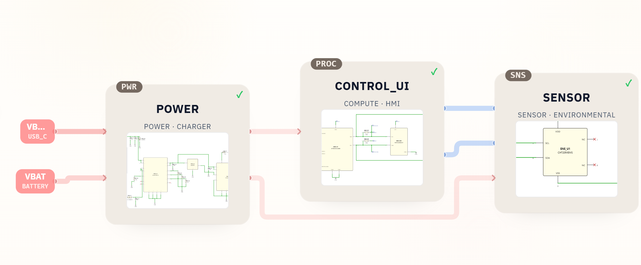
SpeedUp turned a short home-device prompt into a reviewable temperature humidity sensor KiCad project. The generated package includes a top-level schematic, hierarchical module schematics, local symbol and footprint libraries, a BOM, and a downloadable KiCad project ZIP.
The design follows the prompt closely: it is battery powered, charges through USB-C, displays live temperature and humidity on a small screen, and uses an I2C environmental sensor. This is a first engineering draft for review, not a production-ready reference design.
Project Summary
| Field | Details |
|---|---|
| Project | Home temperature and humidity sensor |
| Input | Natural-language product prompt |
| Output | KiCad project with schematic hierarchy, BOM, symbols, and footprints |
| Key modules | POWER, CONTROL_UI, SENSOR |
| Main parts | BQ24074RGTR, TPS63031DSKR, ATTINY816-MNR, CHT20MEMS, HS91L02W2C01 |
| Download | KiCad project ZIP with BOM and local libraries |
| Not included | PCB layout, firmware, enclosure design, calibration data, and compliance validation |
| Status | First engineering draft for review |
The Prompt
The project starts with this product request:
design a temp/humidity sensor using at home,power by battery and charging by type-c,using small screen to display real time temperature and humidity
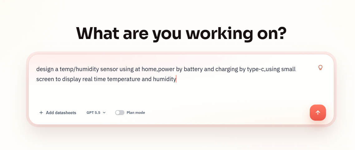
The prompt is compact, but it gives enough constraints to shape a real hardware architecture: home use, battery operation, USB-C charging, live environmental sensing, and a small local display.
What SpeedUp Generated
From that prompt, SpeedUp generated a KiCad project organized around three reviewable blocks:
POWER: USB-C input, battery connector, charge management, protection, voltage supervision, and 3.3 V rail generationCONTROL_UI: anATTINY816-MNRcontroller, OLED display connection, and I2C pullupsSENSOR: aCHT20MEMStemperature and humidity sensor on the shared I2C bus- A top-level schematic tying together
VBAT,VBUS,3V3,I2C0_SCL, andI2C0_SDA - A BOM with 20 line items and 32 placed quantities
The useful thing here is not just the block diagram. The ZIP contains actual KiCad source files, module sheets, symbol libraries, footprint libraries, and BOM exports, which makes the output a concrete engineering starting point.
Want to create a USB-C environmental sensor?
Describe your own USB-C temperature and humidity sensor requirements and create a free account to start a reviewable engineering draft.
Project Architecture
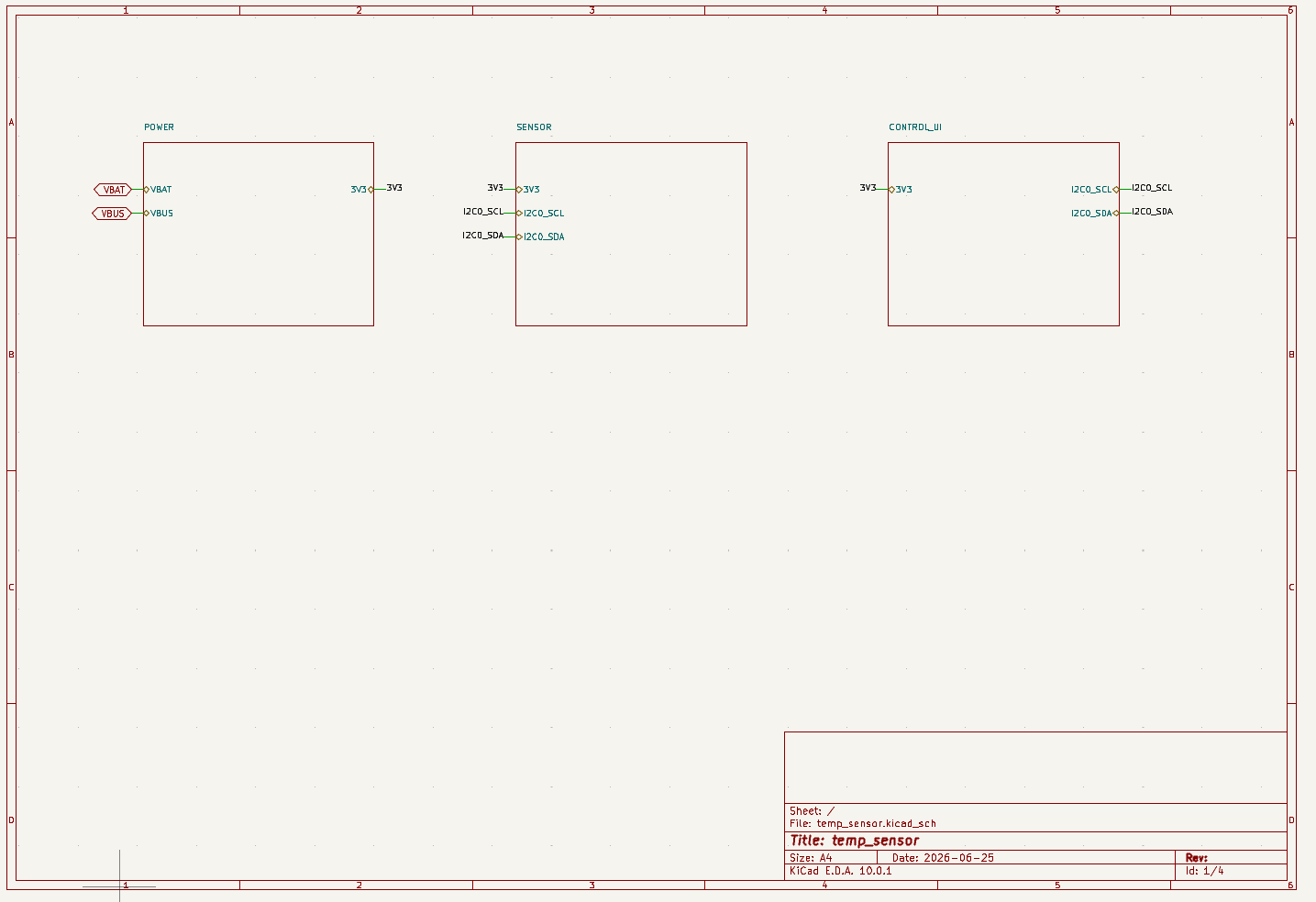
The system is intentionally simple. The power block accepts USB-C and battery input, creates a regulated 3V3 rail, and exposes that rail to the sensing and display sections. The control/display block provides the local UI, while the sensor block sits on the I2C bus and reports real-time temperature and humidity.
That hierarchy is a good fit for a small home sensor because each review area is isolated. Power, sensing accuracy, display behavior, and firmware can be checked separately before the design moves into board layout.
Power and Charging Path
The BOM shows a dedicated charging and regulation chain rather than a generic battery symbol. Key power parts include:
PWR_J1: USB-C connector, listed asTYPE-C 6P(073)PWR_J2: JST-PH-2 battery connector, listed asB2B-PH-K-S(LF)(SN)PWR_U1:BQ24074RGTRbattery chargerPWR_U3:TPS63031DSKRbuck-boost regulator for the 3.3 V system railPWR_U2:MAX809SsupervisorPWR_D1andPWR_D2: USB and ESD protection partsPWR_F1: resettable fuse or input protection element
For a battery powered temperature humidity sensor, this is one of the most important parts of the design to review. Engineers should check charge-current programming, USB-C configuration resistors, battery protection assumptions, regulator stability, inductor saturation current, sleep-mode current, and thermal behavior near the environmental sensor.
Control and Display Subsystem
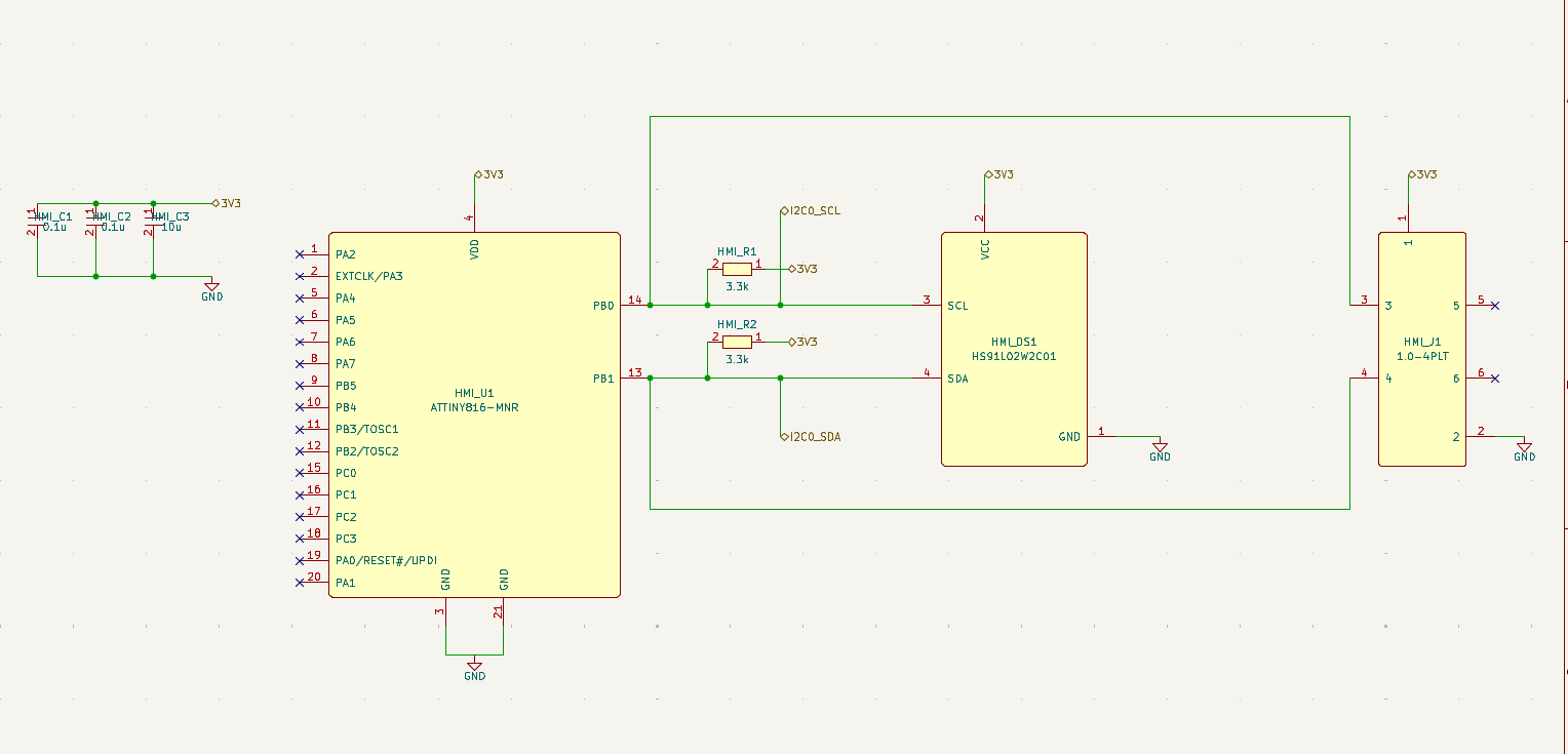
The generated control sheet uses an ATTINY816-MNR microcontroller with a small OLED display module labeled HS91L02W2C01. The schematic also includes I2C pullups and local decoupling around the controller and display path.
This section defines how the device will read environmental data and present it locally. Before production, the firmware team still needs to confirm the OLED interface, display refresh timing, sleep behavior, wake behavior, and how often sensor readings should update to balance battery life against responsiveness.
Temperature and Humidity Sensor Subsystem
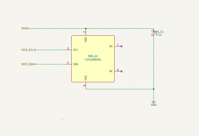
The environmental sensing section is compact: a CHT20MEMS sensor connects to 3V3, I2C0_SCL, and I2C0_SDA, with local decoupling nearby. That is a sensible interface for a small home sensor, and it keeps the schematic easy to inspect.
The BOM also includes an important placement note for the sensor: it should sit near an enclosure vent, be protected from splash and dust, stay thermally isolated from the charger, regulator, display, and processor, and keep its sensing aperture free of coating or residue. That note matters because a temperature and humidity sensor can be electrically correct but physically inaccurate if it is placed next to heat sources or trapped inside an unvented enclosure.
BOM Preview
The generated BOM includes 20 line items and 32 placed quantities. Representative parts include:
| References | Quantity | MPN | Review focus |
|---|---|---|---|
PWR_U1 |
1 | BQ24074RGTR |
Battery charging behavior, charge current, thermal behavior |
PWR_U3 |
1 | TPS63031DSKR |
3.3 V rail stability, inductor choice, load transients |
PWR_J1 |
1 | TYPE-C 6P(073) |
USB-C pinout, CC resistors, mechanical fit |
PWR_J2 |
1 | B2B-PH-K-S(LF)(SN) |
Battery connector orientation and retention |
HMI_U1 |
1 | ATTINY816-MNR |
Firmware, I2C timing, low-power operation |
HMI_DS1 |
1 | HS91L02W2C01 |
OLED interface, mounting height, display current |
SNS_U1 |
1 | CHT20MEMS |
Sensor placement, calibration, airflow, contamination |
PWR_D1 |
1 | USBLC6-2SC6 |
USB/ESD protection strategy |
This BOM is strong enough for a first review pass, but it is not a sourcing-ready production BOM. Lifecycle status, authorized distributor availability, package verification, footprint validation, alternates, and cost targets still need to be checked.
What Still Needs Human Review
Before this temperature humidity sensor becomes a production design, review should focus on:
- USB-C charging behavior, charge-current programming, battery safety, and ESD protection
- 3.3 V rail sizing, regulator stability, inductor selection, and sleep-mode current
- Sensor accuracy, calibration plan, enclosure venting, dust and splash protection, and thermal isolation from warm parts
- OLED display current, visibility, refresh behavior, mounting height, and connector/mechanical fit
ATTINY816-MNRfirmware, programming access, I2C pullups, address conflicts, and power-state handling- Footprint and symbol validation for every package in the local libraries
- PCB placement, copper pours, grounding, thermal paths, and final design-rule checks
Related SpeedUp Projects and Guides
- Use the battery-powered sensor circuit checklist to review charging, regulation, sleep current, and sensor interfaces.
- Follow the AI-generated KiCad schematic review guide before layout or sourcing.
- Compare this sensor with the nRF54L15 KiCad development-board project for a wireless MCU and RF-focused example.
FAQ
Is this temperature humidity sensor production ready?
No. It is a first engineering draft intended for review and iteration. The KiCad project, schematic hierarchy, BOM, and libraries are present, but the design still needs human electrical review, PCB layout, firmware, enclosure validation, calibration, and safety checks.
Does the download include the KiCad source files?
Yes. The downloadable ZIP includes the generated KiCad project, top-level schematic, module schematics, symbol libraries, footprint libraries, and BOM exports.
Does it include a PCB layout?
No PCB layout was found in the provided project package. Treat the files as a schematic and BOM starting point, not as a complete board release.
Why use USB-C charging for a home sensor?
USB-C charging makes the device easier to recharge while keeping the sensor portable. The design still needs careful review of charging current, battery protection, heat generation, and enclosure airflow.
Can SpeedUp generate a similar project from another prompt?
Yes. SpeedUp is designed to turn a natural-language device idea into structured engineering artifacts that can be reviewed, modified, and refined.
Download the KiCad Project
Use this temperature humidity sensor ZIP as a review starting point for the generated KiCad project. The package includes the KiCad schematic hierarchy, local symbols, local footprints, BOM files, and source project files; add PCB layout, firmware, enclosure/mechanical validation, calibration, sourcing checks, and production safety review before treating it as a complete engineering handoff.
Create Your Own Environmental Sensor
Turn your own USB-C temperature and humidity sensor brief into reviewable engineering artifacts.
Use SpeedUp to generate structured schematic sheets and an editable KiCad project for engineering review. Create a free account to begin.
Comments
No comments yet.
Leave a Reply